Waste incineration treatment device
A processing device and waste incineration technology, which is applied in incinerators, combustion methods, combustion types, etc., can solve the problems of insufficient combustion of waste, clogging of combustion devices, and difficulty in cleaning smoke and dust.
- Summary
- Abstract
- Description
- Claims
- Application Information
AI Technical Summary
Problems solved by technology
Method used
Image
Examples
Embodiment 1
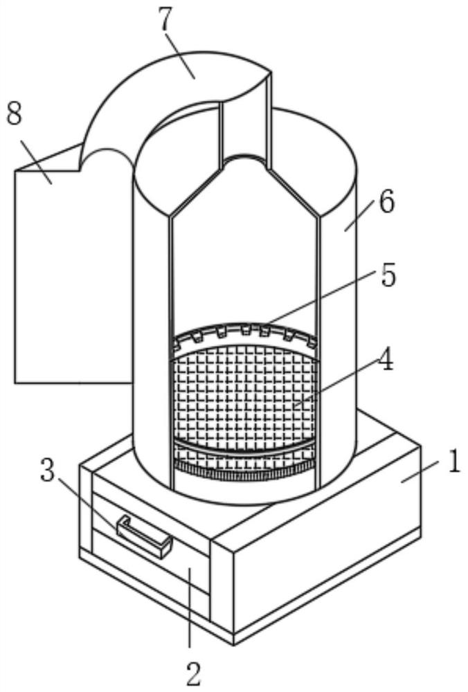
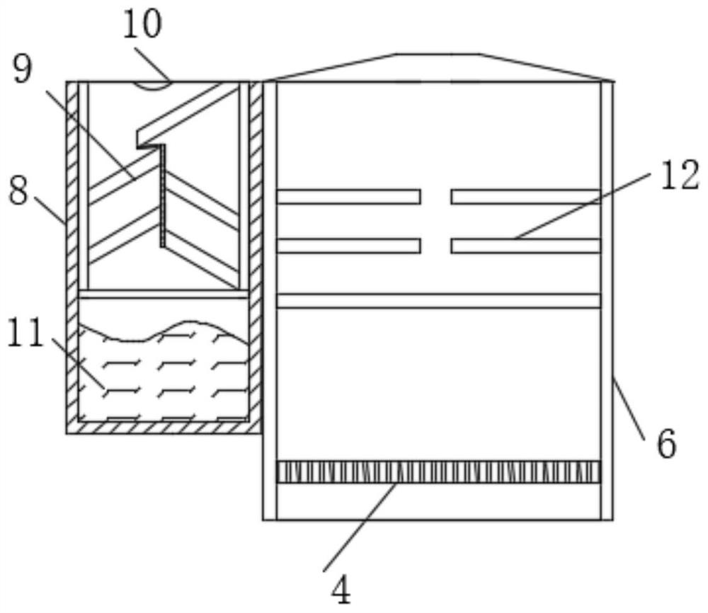
[0032] see Figure 1-2 , the embodiment of the present invention provides a technical solution: a garbage incineration treatment device, including a dust collection box 1, the interior of the dust collection box 1 is movably connected with a dust removal box 2, and one side of the dust removal box 2 is fixedly connected with a handle 3. One side of the dust collection box 1 is connected with a combustion case 6, the top of the combustion case 6 is connected with a ventilation pipe 7, one side of the combustion case 6 is fixedly connected with a flue gas treatment box 8, and the ventilation pipe 7 extends to the flue gas treatment box 8, the inner wall of the combustion case 6 is fixedly connected with an ignition ring 5, and the inner wall of the combustion case 6 is fixedly connected with a combustion device 4 at the lower side of the ignition ring 5, and the top of the flue gas treatment box 8 is fixedly connected with an atomizing nozzle 10, and the smoke The inner wall of ...
Embodiment 2
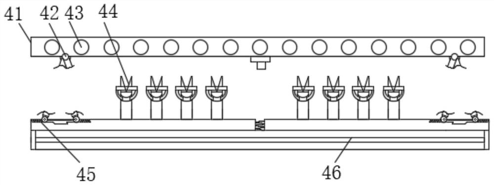
[0035] Such as Figure 1-4As shown, on the basis of Embodiment 1, the present invention provides a technical solution: the combustion device 4 includes a connecting outer frame 41 and a lower receiving sieve plate 46, the lower receiving sieve plate 46 is located on the lower side of the connecting outer frame 41, and the lower The sieve plate 46 is fixedly connected with the inner wall of the combustion chamber 6, and the connecting outer frame 41 is circular, and the inside of the connecting outer frame 41 is fixedly connected with a leakage rail 43, and the lower side of the connecting outer frame 41 is fixedly connected with a moving rod 42. A chute 45 is provided on the side of the receiving sieve plate 46 close to the connecting outer frame 41. The inside of the chute 45 is fixedly connected with a spring, and the moving rod 42 extends to the inside of the chute 45 to be flexibly connected with the chute 45. The upper side of the upper side is fixedly connected with exte...
Embodiment 3
[0038] Such as Figure 1-7 As shown, on the basis of Embodiment 1 and Embodiment 2, the present invention provides a technical solution: the extension rod 44 includes a plate body 445, the upper side of the plate body 445 is fixedly connected with a pushing device 441, and the outer movable sleeve of the pushing device 441 Connected with a restricting ring 442, the outer measuring activity of the restricting ring 442 is connected with a circumscribed ring 444, the restricting ring 442 can shrink into the inside of the circumscribed ring 444, and the opposite side of the restricting ring 442 is movably connected with a rotating arc 443, and the rotating arc The end of the ring 443 away from the restricting ring 442 extends into the inside of the plate body 445 , and the inside of the plate body 445 is fixedly connected with a blocking plug 448 near the rotating arc ring 443 .
[0039] The pushing device 441 includes a left push plate 4416, the left side of the left push plate 4...
PUM
 Abstract
Description
Claims
Application Information
 - R&D
- Intellectual Property
- Life Sciences
- Materials
- Tech Scout
- Unparalleled Data Quality
- Higher Quality Content
- 60% Fewer Hallucinations
Browse by: Latest US Patents, China's latest patents, Technical Efficacy Thesaurus, Application Domain, Technology Topic, Popular Technical Reports.
© 2025 PatSnap. All rights reserved.Legal|Privacy policy|Modern Slavery Act Transparency Statement|Sitemap|About US| Contact US: help@patsnap.com


