
Horizontal axially split pump for guiding leaked liquid

A horizontal split and liquid technology, which is applied to components of pumping devices for elastic fluids, liquid fuel engines, pumps, etc., can solve the problems of leaking liquid diversion, good reliability, and low cost

Pending Publication Date: 2021-06-08
西安航天泵业有限公司
View PDF7 Cites 0 Cited by
  • Summary
  • Abstract
  • Description
  • Claims
  • Application Information

AI Technical Summary

Problems solved by technology

[0005] The purpose of the present invention is to solve the problem that the sealing method of the existing horizontal split pump cannot take into account the problems of simple process, low cost and good reliability, and propose a horizontal split pump that realizes leakage liquid diversion

Method used


Image

  • Horizontal axially split pump for guiding leaked liquid
  • Horizontal axially split pump for guiding leaked liquid
  • Horizontal axially split pump for guiding leaked liquid

Examples


Embodiment Construction

[0037] The technical solutions of the present invention will be clearly and completely described below in conjunction with the accompanying drawings.

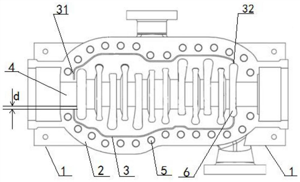
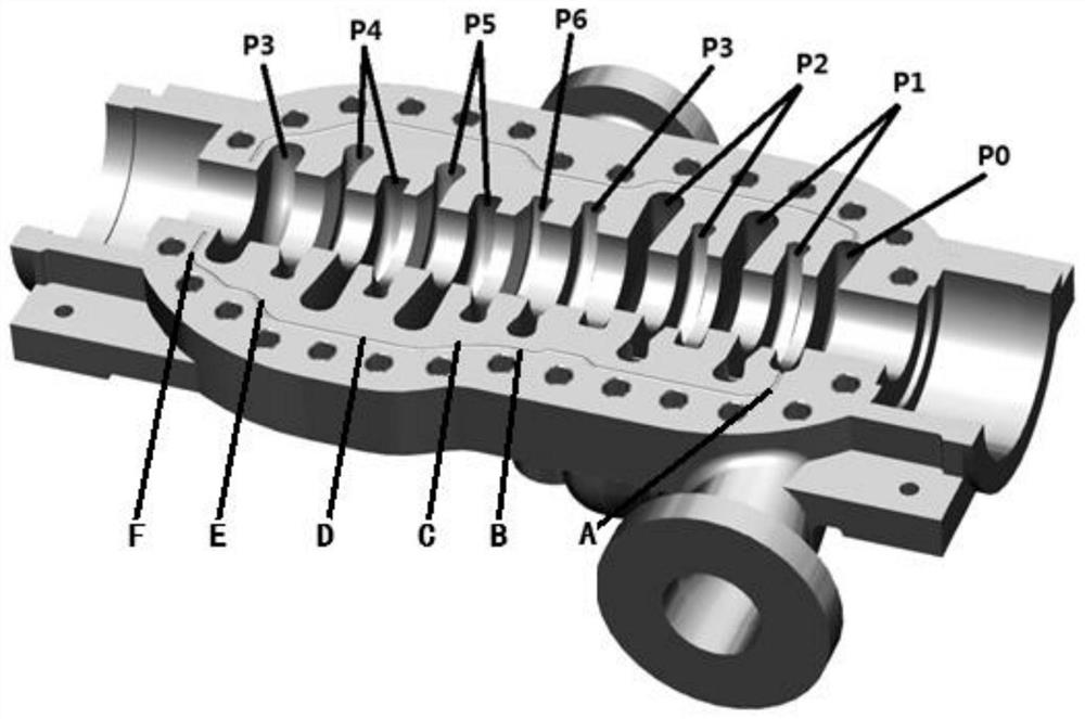
[0038] A horizontal split pump for leaking liquid diversion. On the split surface 2 of the pump body 1, at least one diversion groove 3 is arranged on both sides of the flow channel of the vortex chamber; or on the split surface 2 of the pump cover, the vortex At least one guide groove 3 is provided on both sides of the chamber flow channel; or on the center opening surface 2 of the pump body 1, at least one guide channel 3 is provided on one side of the vortex chamber flow channel, and on the center opening surface 2 of the pump cover , at least one guide groove 3 is provided on the other side of the vortex channel. And the number of guide grooves 3 on both sides of the vortex chamber flow channel is equal, each side guide groove 3 is arranged between the side bolt hole 5 and the vortex chamber flow channel, and the starting e...


PUM


Abstract

The invention relates to a horizontal axially split pump, in particular to a horizontal axially split pump for guiding leaked liquid, and solves the problem that the sealing mode of an existing horizontal axially split pump cannot give consideration to simple process, low cost and good reliability. At least one flow guide groove is formed in each of two sides of a volute chamber flow channel on the axially split surface of a pump body; or at least one flow guide groove is formed in each of two sides of the volute chamber flow channel on the axially split surface of a pump cover; or at least one flow guide groove is formed in one side of the volute chamber flow channel on the axially split surface of the pump body, and at least one flow guide groove is formed in the other side of the volute chamber flow channel on the axially split surface of the pump cover. The number of the flow guide grooves in the two sides of the volute chamber flow channel is equal, and the flow guide grooves in each side are formed between bolt holes in the side and the volute chamber flow channel. The starting end of the flow guide groove on each side is close to a mechanical sealing cavity, and the leading-out end of the flow guide groove is communicated with a suction cavity. By means of the mode that dredging replaces blocking, leaked liquid is guided to the suction cavity through the flow guide grooves, and the sealing difficulty of the axially split surface of the horizontal axially split pump is reduced.

Description

technical field [0001] The invention relates to a horizontal split pump, in particular to a horizontal split pump for realizing leakage liquid diversion. Background technique [0002] The horizontal split pump has the structural characteristics of quick replacement of rotor parts and wearing parts, which can shorten the maintenance time of the pump, and the split face sealing technology and sealing ability are one of the main aspects that limit the application of horizontal split pumps. At the same time, the main manifestation of the leakage of the split pump is the leakage of the split face. [0003] At present, the main methods of split face sealing are hard-to-hard metal seal, flat gasket seal, glue-coated seal, etc. These three methods of sealing have certain effects on split face sealing. Hard-to-hard metal seals require extremely high technology and processing capabilities, and general technology is difficult to achieve; flat gasket seals require high processing techn...

Claims


Application Information

Patent Timeline
Patent Type & Authority Applications(China)
IPC IPC(8): F04D29/42F04D15/00
CPCF04D29/426F04D15/0083
Inventor 王金法段肖雪李永乐许文静王亮亮张高正刘慧娟程建强张世存张鲁
Owner 西安航天泵业有限公司
Learn More