
Concrete processing equipment

A technology for processing equipment and concrete, which is applied in the direction of clay preparation devices, chemical instruments and methods, cleaning methods and utensils, etc., can solve problems such as reducing performance, sticking concrete, and affecting service life, so as to reduce concrete sticking, reduce The effect of concrete solidification and prolonging the service life

Inactive Publication Date: 2021-06-08
赵惠君
View PDF7 Cites 1 Cited by
  • Summary
  • Abstract
  • Description
  • Claims
  • Application Information

AI Technical Summary

Problems solved by technology

[0005] Aiming at the deficiencies of the prior art, the present invention provides a concrete processing equipment, which solves the problem that when the existing concrete processing equipment is stirring concrete, the mixer is easily stuck by stones, making harsh noises, and the inner wall of the container is easily broken. Scratches, in severe cases, the entire machine will be stuck, affecting the service life, and the mixer will stick to a large amount of concrete during the mixing process, which will affect the mixing efficiency of the mixer. When the concrete is solidified, the dust is hard and inconvenient to clean. Used for the first time, reducing the problem of performance

Method used


Image

  • Concrete processing equipment
  • Concrete processing equipment
  • Concrete processing equipment

Examples


Embodiment example 1

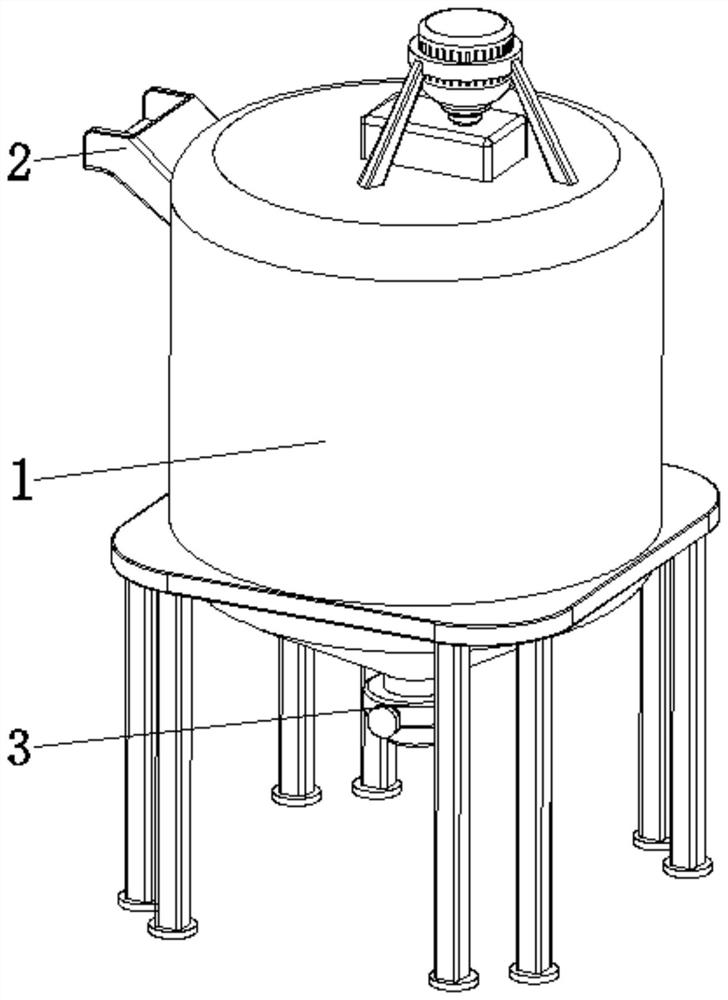
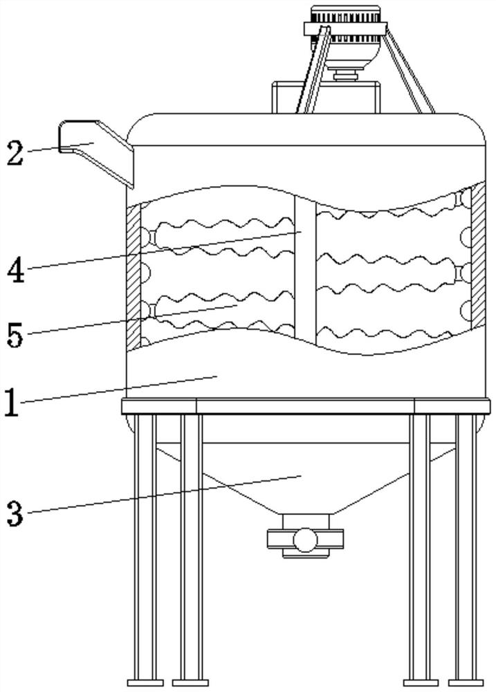
[0032] see Figure 1-7 , the present invention provides a technical solution: a concrete processing equipment, comprising a mixing bin 1, a feeding hopper 2, and a discharging hopper 3, the feeding hopper 2 is arranged on the top side of the surface of the mixing bin 1, and the discharging hopper 3 is arranged At the bottom central position of the mixing bin 1, the interior of the mixing bin 1 is provided with a driving shaft 4, a stirring device 5, an arc-shaped wave peak 6, and an arc-shaped wave trough 7, and the driving shaft 4 is rotatably connected to the top and the inner wall of the mixing bin 1. Between the two sides corresponding to the bottom, the stirring device 5 is fixed on the surface of the driving shaft 4, and the arc-shaped crest 6 and the arc-shaped trough 7 are all arranged on the inner wall of the mixing bin 1, and the arc-shaped crest 6 and the arc-shaped trough 7 are arranged along the mixing chamber 1. The inner wall of the silo 1 is arranged staggered ...


PUM


Abstract

The invention discloses concrete processing equipment. The concrete processing equipment comprises a mixing bin, a feeding hopper and a discharging hopper, wherein the feeding hopper is arranged at one side of the top surface of the mixing bin, the discharging hopper is arranged in the center position of the bottom of the mixing bin, a driving rotating shaft is rotatably connected between two corresponding sides of the top and bottom inner walls of the mixing bin, stirring devices are fixed to a surface of the driving rotating shaft, arc-shaped wave crests and arc-shaped wave troughs are all arranged on an inner wall of the mixing bin, and are arranged in a staggered mode in a circumferential direction of the corresponding inner wall of the mixing bin, and the ends, away from the driving rotating shaft, of the stirring devices are connected with the arc-shaped wave crests and the arc-shaped wave troughs in a matching mode. The invention relates to the technical field of concrete processing. According to the concrete processing equipment, the purposes of jamming prevention and self-cleaning are achieved, the situation of jamming can be avoided, thus the service life is prolonged, and meanwhile, self-cleaning can be conducted, so that concrete adhesion is reduced, stirring is facilitated, and the working efficiency and the use performance are improved.

Description

technical field [0001] The invention relates to the technical field of concrete processing, in particular to concrete processing equipment. Background technique [0002] Concrete refers to the artificial stone made of cement as the main cementitious material, mixed with water, sand, stones, chemical admixtures and mineral admixtures when necessary, mixed in appropriate proportions, uniformly stirred, compacted and cured. Concrete is mainly divided into two stages and states: the plastic state before setting and hardening, that is, fresh concrete or concrete mixture; the hard state after hardening, that is, hardened concrete or concrete. Concrete has abundant raw materials, low cost, and good plasticity. , high strength, good durability, and can be reinforced with steel bars. Concrete mixer is a kind of machine commonly used on construction sites. Its function is mainly to use cement as cementitious material, sand and stone as aggregate, and mix it with water in a certain pr...

Claims


Application Information

Patent Timeline
Patent Type & Authority Applications(China)
IPC IPC(8): B28C5/16B08B5/02
CPCB28C5/16B28C5/0806B28C5/0831B08B5/02
Inventor 赵惠君
Owner 赵惠君
Learn More