Punching clamp
A technology of punching fixture and receiving frame, which is applied in the field of drilling machines, and can solve problems such as easy slipping and deflection of perforating needles, opening of pipe parts, and easy injury of hands, etc.
- Summary
- Abstract
- Description
- Claims
- Application Information
AI Technical Summary
Problems solved by technology
Method used
Image

Examples
Embodiment 1
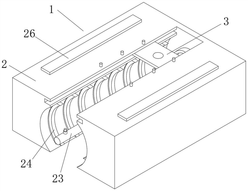
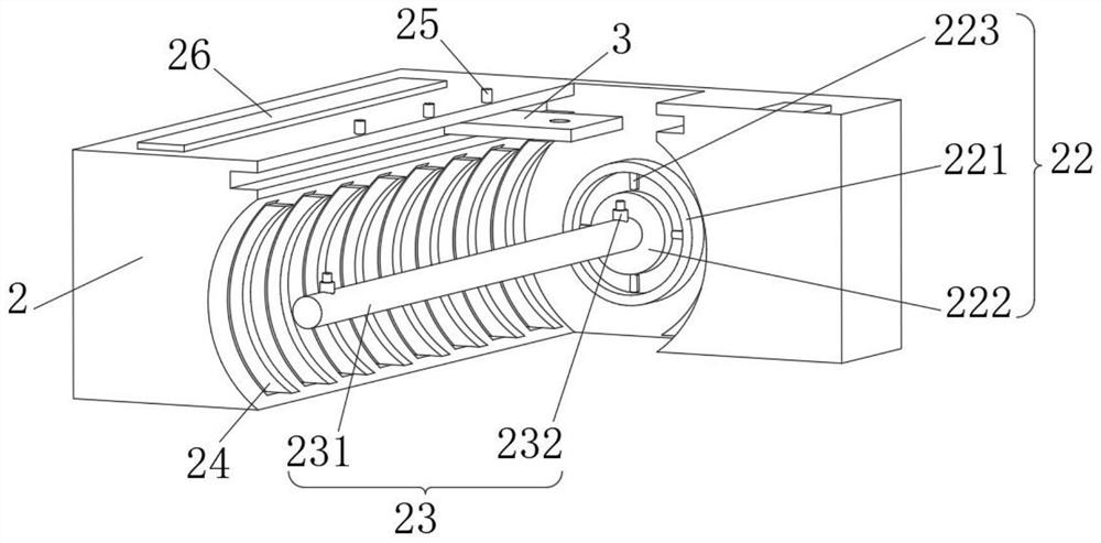
[0038] see Figure 1-2 , the present invention provides a technical solution: a punching jig, comprising a punching jig body 1 composed of a base 2 and a sliding plate 3, the inside of the base 2 slides with the outside of the sliding plate 3, and the inside of the sliding plate 3 is slidingly connected with Puncher, the base 2 includes a receiving frame 21, the inside of the receiving frame 21 is fixedly connected with a locator 22, and the side of the locator 22 away from the receiving frame 21 is fixedly connected with a positioning rod 23, and the inside of the receiving frame 21 is slidingly connected with an extrusion 24, the inside of the receiving frame 21 is slidably connected with the outside of the sliding plate 3 through the slideway, and the internal screw connection of the receiving frame 21 is connected with a rotating block 25, and the bottom of the rotating block 25 runs through the sliding plate 3 and extends to the inside of the slideway. The inside of the f...
Embodiment 2
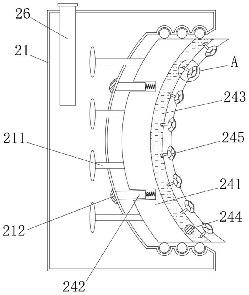
[0043] see Figure 1-3 , on the basis of Embodiment 1, the present invention provides a technical solution: the squeezer 24 includes a squeeze block 241, the outside of the squeeze block 241 is slidingly connected with the inside of the receiving frame 21 through a rotating bead, and the inside of the receiving frame 21 Filled with hydraulic oil, the inside of the receiving frame 21 is slidably connected with a buoyant block 211 , the right side of the buoyant block 211 is attached to the left side of the extruding block 241 , and the inner wall of the receiving frame 21 is fixedly connected with a magnetic block 212 .
[0044] The left side of the extruding block 241 is fixedly connected with a magnetic strip 242 through a spring group, and a storage cavity 243 is opened inside the extruding block 241 , and an opening and closing valve 244 is threadedly connected to the interior of the extruding block 241 .
[0045] The bottom of the opening and closing valve 244 runs through...
Embodiment 3
[0048] see Figure 1-5 , On the basis of Embodiment 1 and Embodiment 2, the present invention provides a technical solution: the anti-skid device 245 includes a sponge ball 2451, the left side of the sponge ball 2451 communicates with the interior of the storage chamber 243 through an adsorption rod, and the sponge ball 2451 The outer side of the sponge ball 2451 is connected with a sponge strip 2452, and the inside of the sponge ball 2451 is fixedly connected with a rebound bladder 2453.
[0049] The electromagnet 232 includes an electromagnetic rod 2321 , the inside of the electromagnetic rod 2321 is rotatably connected with a protective ball 2322 through a rotating shaft, and the outer side of the protective ball 2322 is fixedly connected with a friction block 2323 .
[0050] The outside of the friction block 2323 is fixedly connected with a pneumatic bag 2324 through an elastic ball, the bottom of the pneumatic bag 2324 is fixedly connected with the inside of the protectiv...
PUM
 Abstract
Description
Claims
Application Information
 - R&D
- Intellectual Property
- Life Sciences
- Materials
- Tech Scout
- Unparalleled Data Quality
- Higher Quality Content
- 60% Fewer Hallucinations
Browse by: Latest US Patents, China's latest patents, Technical Efficacy Thesaurus, Application Domain, Technology Topic, Popular Technical Reports.
© 2025 PatSnap. All rights reserved.Legal|Privacy policy|Modern Slavery Act Transparency Statement|Sitemap|About US| Contact US: help@patsnap.com