
Implosion detection device for catalytic debinding furnace

A detection device and catalytic degreasing technology, which is applied in the direction of furnace monitoring devices, furnaces, furnace components, etc., can solve the problems of lack of, recording function technology, no function technology, etc., and achieve the effect of simple structure, convenient use, and improved safety

Active Publication Date: 2021-06-08
广州达运医疗科技有限公司
View PDF4 Cites 0 Cited by
  • Summary
  • Abstract
  • Description
  • Claims
  • Application Information

AI Technical Summary

Problems solved by technology

[0003] Degreasing treatment generally needs to put the molded body into a catalytic degreasing furnace for heating, exhaust, catalysis, decomposition and other processes. During the working process of the catalytic degreasing furnace, when Many factors such as unreasonable material composition, improper manual operation or wrong data parameters will cause implosion inside the catalytic degreasing furnace. Because the scale of the implosion varies, generally it will not cause too many work accidents. When an implosion occurs, it is generally determined by the staff whether an implosion has occurred internally. At present, there is no functional technology for reminding when the implosion occurs, and there is no functional technology for recording when the implosion occurs. However, due to some The development of new products is summed up after many failures. Therefore, it is necessary to detect and record when implosion occurs, and such technology is lacking in the prior art

Method used


Image

  • Implosion detection device for catalytic debinding furnace
  • Implosion detection device for catalytic debinding furnace
  • Implosion detection device for catalytic debinding furnace

Examples


Embodiment Construction

[0020] The present invention will be further described below in conjunction with accompanying drawing description and specific embodiment:

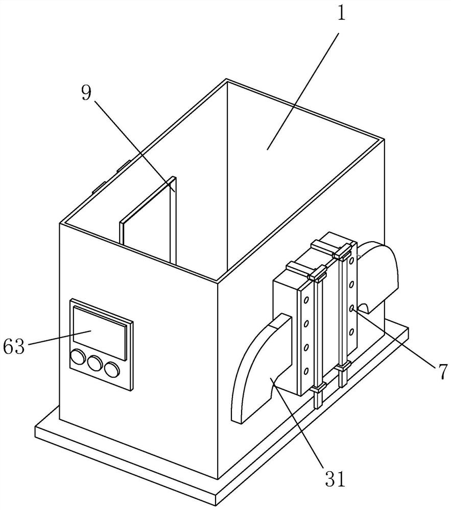
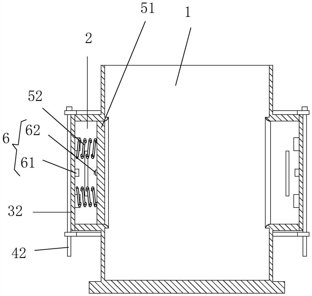
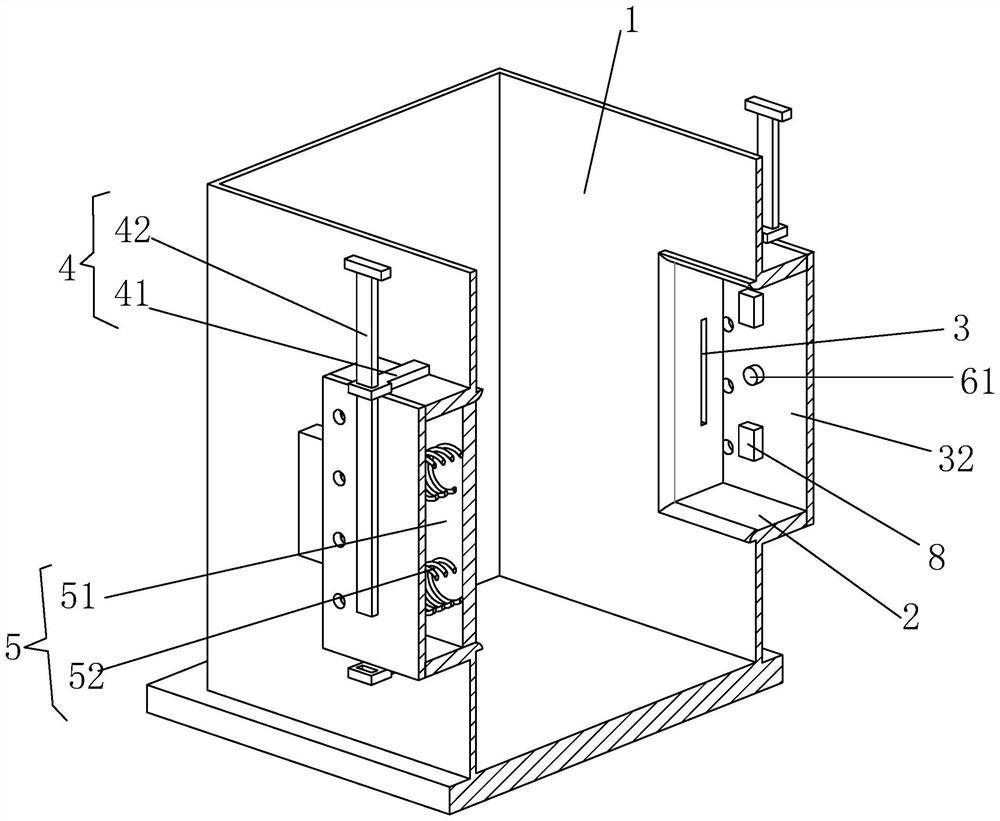
[0021] Such as Figures 1 to 3 Shown a kind of catalytic degreasing furnace implosion detection device, comprises body of heater 1, is provided with cavity 2 in described body of heater 1 both sides, is provided with vent hole 3 in both sides in described cavity 2, in the One side of the air release hole 3 is provided with an air release pipe 31, and one side of the cavity 2 is provided with a back plate 32, and the cavity 2 is provided with a locking structure 4 that fixes the back plate 32. 2 is provided with a buffer structure 5, and a detection device 6 is provided between the back plate 32 and the buffer structure 5. During use, when an implosion occurs, the gas is buffered by the buffer structure in the cavity, and the buffer structure is in the cavity Move in the body until the gas can be discharged from the air release hole. At t...


PUM


Abstract

The invention discloses an implosion detection device for a catalytic debinding furnace. The device comprises a furnace body, wherein cavities are arranged in the two sides of the furnace body; vent holes are arranged in the two sides in the cavities; vent pipes are arranged at one sides of the vent holes; back plates are arranged at one sides of the cavities; locking structures for fixing the back plates are arranged on the cavities; buffer structures are arranged in the cavities; and detection devices are arranged between the back plates and the buffer structures. The implosion detection device is simple in structure, when the furnace body implodes, expanded air during implosion is buffered through the buffer structures, deflation is conducted through the vent holes, the detection devices record the number of times of implosion, a controller makes a sound to remind workers, research and development and improvement of new materials and new finished products by researchers are facilitated through detection records of implosion, in addition, the locking structures are additionally arranged at the positions of the back plates, damage to the back plates is prevented, and the safety of the implosion detection device is remarkably improved through the arrangement of the locking structures and the vent holes.

Description

technical field [0001] The invention relates to the field of powder metallurgy equipment, in particular to an implosion detection device for a catalytic degreasing furnace. Background technique [0002] Metal powder injection molding is a new type of powder metallurgy molding technology. After the metal powder particles are mixed with the binder to form a mixture, the molded blank is formed by injection molding. A certain amount of binder in the body must be removed before the molded blank is sintered. degreasing [0003] Degreasing treatment generally requires putting the molded body into a catalytic degreasing furnace for heating, exhaust, catalysis, and decomposition. Aspects of factors will cause implosion inside the catalytic degreasing furnace. Because the scale of the implosion varies, generally it will not cause too many work accidents. When the implosion occurs, the staff generally derives the internal Whether an implosion occurs, there is currently no functional ...

Claims


Application Information

Patent Timeline
Patent Type & Authority Applications(China)
IPC IPC(8): B22F3/10F27D21/04
CPCB22F3/1025B22F3/003F27D21/04F27D2021/005
Inventor 冯健
Owner 广州达运医疗科技有限公司
Learn More