A method for evaluating residual stress distribution characteristics of natural gas pipeline girth welds using coercive force

A natural gas pipeline, residual stress technology, applied in the direction of using stable tension/pressure to test material strength, force/torque/work measuring instruments, instruments, etc., can solve the high requirements of ultrasonic measurement conditions, artificial drilling, pipeline damage and other problems, to achieve the effect of high evaluation efficiency, high precision and simple operation

Active Publication Date: 2022-08-02
CHINA UNIV OF PETROLEUM (EAST CHINA)
View PDF0 Cites 0 Cited by
  • Summary
  • Abstract
  • Description
  • Claims
  • Application Information

AI Technical Summary

Problems solved by technology

[0003] At present, the blind hole method and the ultrasonic method are mostly used for the measurement of the residual stress of the pipeline on site. However, since the blind hole method is a destructive detection method, the pipeline needs to be artificially drilled during the measurement, causing damage to the pipeline; the measurement conditions of the ultrasonic method are demanding and difficult. It is easy to be affected by factors such as material anisotropy, processing technology, heat-affected zone, etc. Therefore, it is urgent to propose a new and efficient online evaluation method for residual stress in pipelines, which can not only ensure the service safety of welded pipelines, but also ensure the safety of pipelines. residual stress evaluation

Method used


Image

  • A method for evaluating residual stress distribution characteristics of natural gas pipeline girth welds using coercive force
  • A method for evaluating residual stress distribution characteristics of natural gas pipeline girth welds using coercive force
  • A method for evaluating residual stress distribution characteristics of natural gas pipeline girth welds using coercive force

Examples


Embodiment Construction

[0033] The specific embodiments of the present invention will be further described below in conjunction with the accompanying drawings and specific embodiments:

[0034] A method for evaluating residual stress distribution characteristics of a natural gas pipeline girth weld by using coercive force, which specifically includes the following steps:

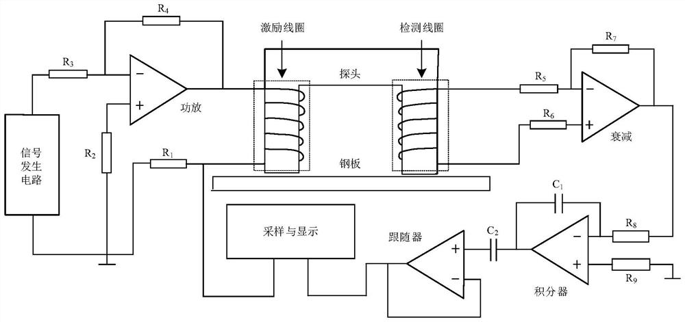
[0035] Step 1, the probe of the coercivity detection device is closely attached to the outer wall of the natural gas pipeline. In this embodiment, the coercivity detection device adopts a U-shaped probe, and the magnetic core of the U-shaped probe is made of manganese-zinc ferrite. The coils are wound on both sides of the magnetic core, and the induction coil can also be used as a detection coil to detect the change of the magnetic induction intensity in the magnetic circuit during the magnetization process; the probe and the outer wall of the natural gas pipeline form a closed loop, and the coercive force detection device is turned...


PUM

PropertyMeasurementUnit
lengthaaaaaaaaaa
radiusaaaaaaaaaa
thicknessaaaaaaaaaa

Abstract

The invention discloses a method for evaluating residual stress distribution characteristics of a natural gas pipeline girth weld by using coercive force. The method utilizes the probe of the coercive force detection device and the outer wall of the natural gas pipeline to form a closed magnetic circuit, and an alternating current is passed into the probe to magnetize the closed magnetic circuit to measure the hysteresis loop, and the same material as the natural gas pipeline is used to make a standard tensile The test piece is subjected to stress test to determine the corresponding relationship between coercive force and stress, and then use the coercive force detection device to measure the residual stress of the outer wall of the natural gas pipeline, draw the residual stress change curve, and establish a finite element model according to the actual natural gas pipeline. The spherical heat source model simulates the distribution of residual stress at the girth weld of the natural gas pipeline, determines the residual stress distribution cloud map at the girth weld, draws the residual stress characteristic curve and verifies its accuracy. The invention realizes the nondestructive detection and evaluation of the residual stress of the natural gas pipeline, has simple operation, and is beneficial to guarantee the service safety of the welded pipeline.

Description

technical field [0001] The invention relates to the field of natural gas pipeline construction, in particular to a method for evaluating residual stress distribution characteristics of a natural gas pipeline girth weld by using coercive force. Background technique [0002] Pipeline girth weld welding technology, as a key technology for on-site construction of natural gas pipelines, will inevitably generate welding residual stress during the welding process. The existence of residual stress is the cause of failure modes such as brittle fracture, fatigue fracture and stress corrosion cracking of pipeline welded joints. Therefore, it is of great significance to study the distribution characteristics of residual stress for the long-term effectiveness and safety of in-service pipelines. [0003] At present, the blind hole method and ultrasonic method are mostly used for the measurement of residual stress in the pipeline. However, because the blind hole method belongs to the destr...

Claims


Application Information

Patent Timeline
Patent Type & Authority Patents(China)
IPC IPC(8): G01L5/00G01N3/08G01R33/14
CPCG01L5/0047G01N3/08G01R33/14
Inventor 李玉坤王鄯尧朱建平蒋毅冯淑路王垒超鲁青龙曹小建彭启凤杨进川王龙升李坤程磊
Owner CHINA UNIV OF PETROLEUM (EAST CHINA)
Why Eureka
Try Eureka