Sintering furnace for aluminum oxide ceramic production

A technology of alumina ceramics and sintering furnace, applied in the field of sintering furnace, can solve the problems of large frying furnace, sintering furnace, single structure design, etc.

Inactive Publication Date: 2021-06-04
DONGTAI SMILE NEW MATERIAL TECH
View PDF6 Cites 0 Cited by
  • Summary
  • Abstract
  • Description
  • Claims
  • Application Information

AI Technical Summary

Problems solved by technology

[0005] The present invention aims to solve the problem that the structure design of the existing sintering furnace for the production of alumina ceramics is single. When the existing device is used, outside personnel cannot effectively observe the internal temperature, so that the device fails when the internal temperature reaches a critical value, and the alumina ceramics Due to the failure of the internal device of the sintering furnace for production, the internal temperature rises and the internal pressure of the sintering furnace is too large, and the phenomenon of frying the furnace occurs later, which is not conducive to practical use. A sintering furnace for the production of alumina ceramics is provided, so that the device can be used in In actual use, by setting up temperature sensors, temperature displays and cooling water pipes, external personnel can effectively observe the internal temperature, so that external personnel can make emergency treatment in time to prevent the internal temperature from reaching a critical value, and make alumina ceramics production When there is a failure inside the sintering furnace, the temperature of the furnace body can be cooled through the cooling water pipe to avoid the phenomenon of frying the furnace, which is very practical

Method used


Image

  • Sintering furnace for aluminum oxide ceramic production
  • Sintering furnace for aluminum oxide ceramic production
  • Sintering furnace for aluminum oxide ceramic production

Examples


Embodiment

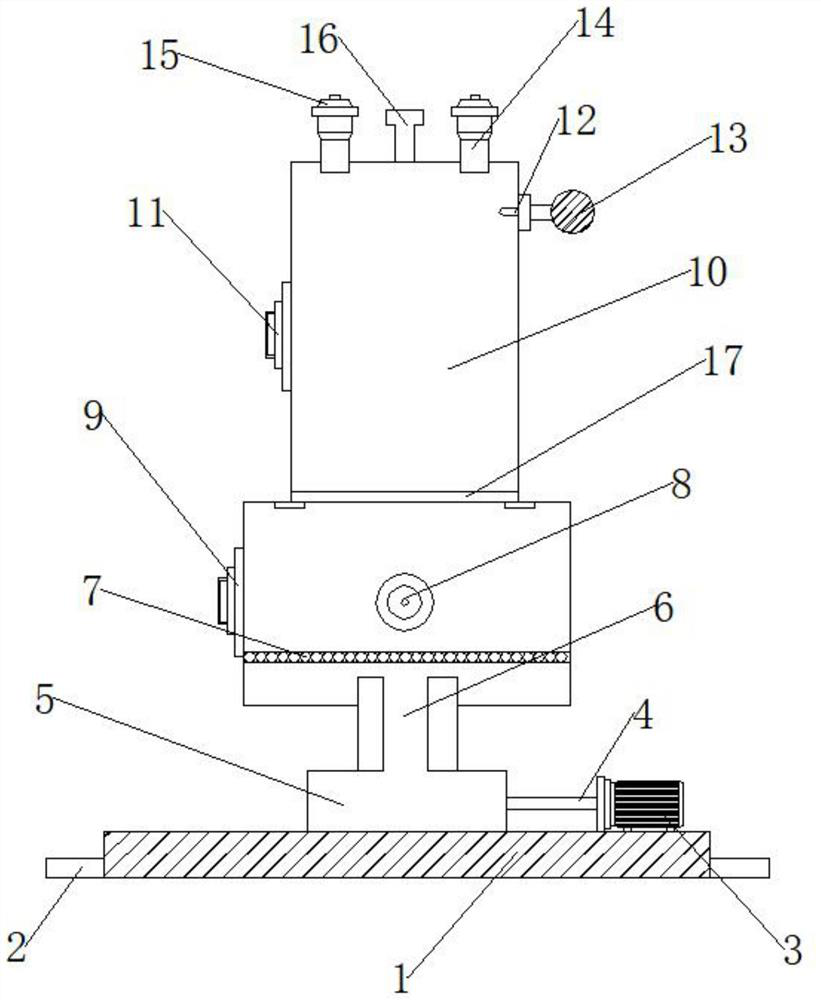
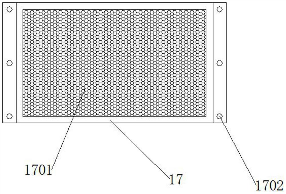
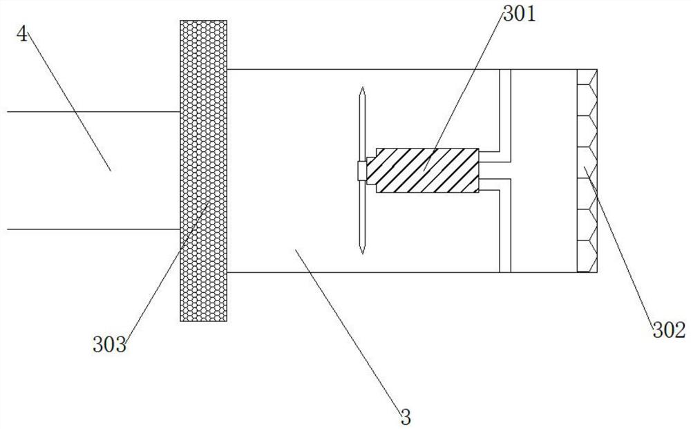
[0025] refer to Figure 1-4 ,

[0026] A sintering furnace for the production of alumina ceramics provided in this embodiment includes a bottom base 1, a fixed plate 2, a fan 3 and an air inlet pipe 4, the fixed plate 2 is located on one side of the bottom base 1, and the fixed plate 2 and the The bottom base 1 is fixedly connected, the right side of the bottom base 1 is provided with a fan 3, and one side of the fan 3 is provided with an air inlet pipe 4, and the air inlet pipe 4 is connected through the fan 3, and the upper end of the bottom base 1 is provided with There is a boiler base 5, and the boiler base 5 is fixedly connected to the bottom base 1, the upper end of the boiler base 5 is provided with a boiler air inlet 6, and the boiler air inlet 6 is connected through the boiler base 5, and the boiler air inlet 6 The upper end is provided with a boiler main body 7, and one side of the boiler main body 7 is provided with a boiler ignition port 8, and the left side of t...


PUM


Abstract

The invention provides a sintering furnace for aluminum oxide ceramic production, and belongs to the technical field of sintering furnaces. The sintering furnace comprises a bottom base, a fixing plate, a fan and an air inlet pipe, wherein the fixing plate is located on one side of the bottom base and fixedly connected with the bottom base, the fan is arranged on the right side of the bottom base, the air inlet pipe is arranged on one side of the fan, the air inlet pipe is in through connection with the fan, a boiler base is arranged at the upper end of the bottom base, and the boiler base is fixedly connected with the bottom base. According to the sintering furnace for the aluminum oxide ceramic production, through structural improvement, when the sintering furnace is actually used, by arranging a temperature sensor and a temperature displayer, the external personnel can effectively observe an internal temperature condition and can make emergency treatment in time, an internal temperature is prevented from reaching a critical value, by arranging a cooling water pipe, when the interior of the sintering furnace for the aluminum oxide ceramic production breaks down, a furnace body can be cooled by means of the cooling water pipe, a furnace explosion phenomenon is avoided, and practicability is high.

Description

technical field [0001] The invention relates to the technical field of sintering furnaces, in particular to a sintering furnace for producing alumina ceramics. Background technique [0002] The sintering furnace refers to the special equipment for obtaining the required physical and mechanical properties and microstructure of the powder compact through sintering. The sintering furnace is used to dry the slurry on the silicon wafer, remove the organic components in the slurry, and complete the aluminum back field and Grid wire sintering, however, there are still various problems in the various sintering furnaces for the production of alumina ceramics on the market. [0003] However, when the existing sintering furnaces for alumina ceramic production are actually used, outside personnel cannot effectively observe the internal temperature, so that the device fails when the internal temperature reaches a critical value, and the sintering furnace for alumina ceramic production is...

Claims


Application Information

Patent Timeline
Patent Type & Authority Applications(China)
IPC IPC(8): F27B17/00F27D21/00F27D9/00C04B35/10
CPCF27B17/0041F27D21/0014C04B35/10F27D2009/0013F27M2003/04
Inventor 奚卫平
Owner DONGTAI SMILE NEW MATERIAL TECH
Why Eureka
Try Eureka