Magnetic suspension valve seat device

A magnetic levitation valve and valve seat technology, which is applied in valve device, valve operation/release device, valve device for absorbing fluid energy, etc., can solve problems such as energy waste, valve seat ball wear, and reduction of valve seat sealing effect, etc. To achieve the effect of improving the service life

Pending Publication Date: 2021-06-04
OULAM VALVE TECH CO LTD
View PDF0 Cites 0 Cited by
  • Summary
  • Abstract
  • Description
  • Claims
  • Application Information

AI Technical Summary

Problems solved by technology

[0003] The existing valve seat is generally made of rubber, which is easy to wear between the ball and the ball after a period of use, which reduces the sealing effect of the valve seat, so the valve seat needs to be replaced continuously, and the replaced old valve seat cannot re-use, resulting in a lot of waste of energy

Method used


Image

  • Magnetic suspension valve seat device
  • Magnetic suspension valve seat device

Examples


Embodiment Construction

[0016] In order to make the technical means, creative features, goals and effects achieved by the present invention easy to understand, the present invention will be further elaborated below in conjunction with specific embodiments, but the following embodiments are only preferred embodiments of the present invention, not all. Based on the examples in the implementation manners, other examples obtained by those skilled in the art without making creative efforts all belong to the protection scope of the present invention. The experimental methods in the following examples, unless otherwise specified, are conventional methods, and the materials, reagents, etc. used in the following examples, unless otherwise specified, can be obtained from commercial sources.

[0017] Example:

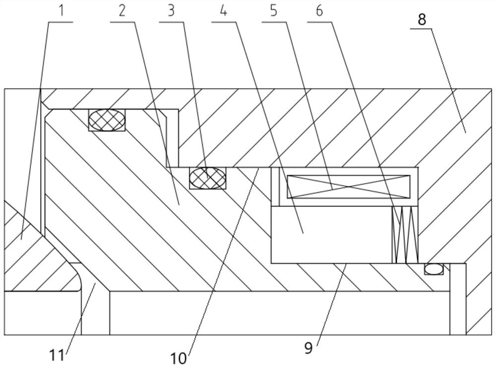
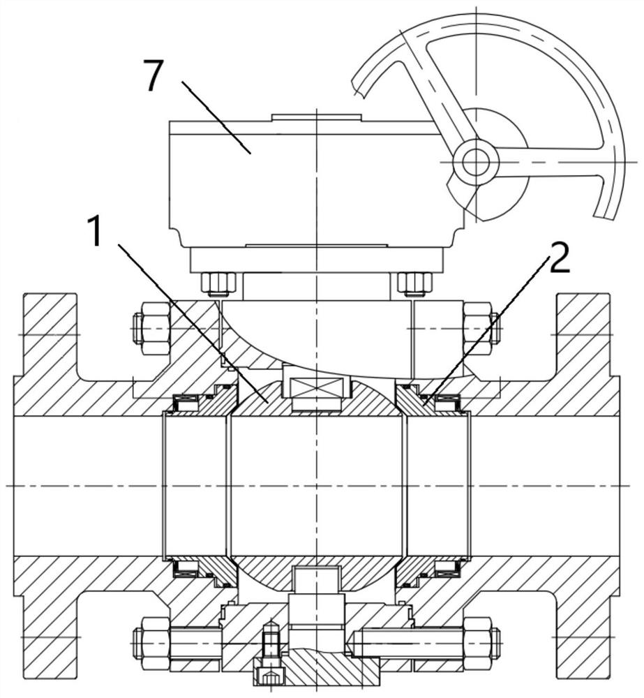
[0018] Such as figure 1 , figure 2 As shown, the present invention provides a magnetic levitation valve seat device, including a valve seat body 2, an installation groove 11 is provided on the inside ...


PUM


Abstract

The invention discloses a magnetic suspension valve seat device which comprises a valve seat body, a mounting groove is formed in the inner side of the valve seat body, a sphere is mounted at the mounting groove, a first step and a second step are arranged on the outer side of the valve seat body, a valve deck is mounted outside the valve seat body, and a magnet is arranged on the first step. A buffering piece is fixed to the other end of the magnet, the other end of the buffering piece is connected with the valve deck, a coil is arranged outside the magnet, a sealing piece is installed in the second step, a sealing piece is fixed to the interior of the side, close to the ball body, of the outer side of the valve seat body, and an actuator is fixedly arranged above the sphere. The device can be turned on and turned off by powering on and powering off the coil, the service life of the device is prolonged, and the device has the advantages of being environmentally friendly, efficient, high in quality and the like.

Description

technical field [0001] The invention relates to the technical field of valve seats, in particular to a magnetic suspension valve seat device. Background technique [0002] Ball valves are used to cut off or connect the medium in the pipeline, and are usually used in hydraulic pipelines or fluid delivery pipelines. Because of their quick and easy opening and closing, and strong flexibility, they are widely used in petroleum, chemical, metallurgical and other industries. The sealing principle is mainly through: a round ball is set inside the valve body, and when the valve is in the open state, the through hole in the middle of the ball is connected with the inlet and outlet at both ends of the valve cover to form a pipeline. When closing, it is only necessary to drive the ball to rotate 90° through the valve stem, so that the center lines of the two are perpendicular to each other, and use the spherical surface of the ball to close the pipeline. In order to prevent internal l...

Claims


Application Information

Patent Timeline
IPC IPC(8): F16K31/06F16K5/06F16K5/20F16K47/02
CPCF16K31/0675F16K31/0644F16K5/06F16K5/0647F16K5/0663F16K5/201F16K47/02
Inventor 金志远王大秋陈阿龙金汉聂钟庚福叶挺
Owner OULAM VALVE TECH CO LTD
Why Eureka
Try Eureka