Radial direct-acting type clamping device
A clamping device, direct-acting technology, used in workpiece clamping devices, manufacturing tools, etc., can solve the problems of long assembly time, complex overall structure, and low degree of automation.
- Summary
- Abstract
- Description
- Claims
- Application Information
AI Technical Summary
Problems solved by technology
Method used
Image

Examples
Embodiment 1
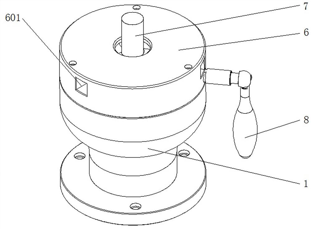
[0028] The main structure of this embodiment, such as figure 1 , figure 2 As shown, it includes the lower base 1 and the upper end cover 6, the end cover 6 is provided with a rotating disc 3, and the middle part of the end cover 6 and the rotating disc 3 is provided with a through hole for the ball head 7 to be inserted into. The upper surface of the disk 3 is also provided with a ball-holding device; the side of the end cover 6 is provided with a number of positioning holes with different functions, and the positioning holes are connected through through grooves; The handle 8 of the hole, the handle 8 can be rotated in the positioning hole of different functions, and drives the ball head holding device on the upper part of the rotating disk 3, so as to realize the different positioning of the ball head 7 inserted into the end cap 6 and the rotating disk 3. GPS.
[0029] The specific implementation is that the ball head holding device has three states: loosening, escape pre...
Embodiment 2
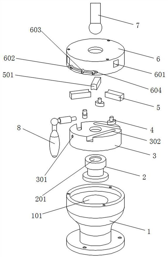
[0034] On the basis of the above-mentioned embodiments, this embodiment further defines the structure of the ball head device, such as figure 1 As shown, the ball head holding device provided on the upper surface of the rotating disk 3 is mainly composed of three sets of clamping mechanisms, and each set of clamping mechanisms is composed of a lower guide block 4 and an upper ball head holding block 5. The upper surface of the rotating disc 3 is provided with three mutually disconnected oblique chute 302, each oblique chute 302 is provided with a guide block 4, and the side of the end cover 6 is evenly distributed with The guide hole 601 matched with the ball joint clamping block 5, one end of each ball joint clamping block 5 is placed in the guide hole 601, and the other end faces the through hole in the middle of the end cover 6, between the adjacent ball joint clamping blocks 5 The angle between them is 120°. When the handle 8 drives the rotating disk 3 to rotate, it drive...
Embodiment 3
[0036]On the basis of the above-mentioned embodiments, this embodiment further defines the structure of the guide block 4 and the ball head holding block 5, such as figure 1 As shown, each of the guide blocks 4 includes a lower slide block and an upper fixed column, and each of the ball head clamping blocks 5 is provided with a blind hole that is sleeved on the upper fixed column of the guide block 4, and each ball head The end surfaces of the clamping block 5 facing the through hole in the middle of the end cover 6 are spherical contours 501 . Since the end surface of the ball head holding block 5 is set to the spherical profile 501 to clamp the ball head 7, it is set to the spherical profile 501, and since one end of the ball head holding block 5 is placed in the guide hole 601, there is no need to fix the guide block 4 With the ball head holding block 5, the fixed column at the top of the guide block 4 and the blind hole at the bottom of the ball head holding block 5 can be...
PUM
 Abstract
Description
Claims
Application Information
 - R&D
- Intellectual Property
- Life Sciences
- Materials
- Tech Scout
- Unparalleled Data Quality
- Higher Quality Content
- 60% Fewer Hallucinations
Browse by: Latest US Patents, China's latest patents, Technical Efficacy Thesaurus, Application Domain, Technology Topic, Popular Technical Reports.
© 2025 PatSnap. All rights reserved.Legal|Privacy policy|Modern Slavery Act Transparency Statement|Sitemap|About US| Contact US: help@patsnap.com