
Machining process for herringbone groove of gear shaft

A processing technology and herringbone groove technology, which is applied in the direction of metal processing equipment, metal processing machinery parts, manufacturing tools, etc., can solve the problems of low work efficiency, poor quality, low efficiency, etc., to reduce labor intensity, improve work efficiency, The effect of improving machining accuracy

Pending Publication Date: 2021-06-04
NANTONG ZHONGLV GEAR CO LTD
View PDF0 Cites 0 Cited by
  • Summary
  • Abstract
  • Description
  • Claims
  • Application Information

AI Technical Summary

Problems solved by technology

Considering that the parts are required to have accurate herringbone groove spherical raceway track, it is also necessary to ensure that the herringbone groove spherical raceway has an accurate position when it rotates, and the track of the raceway must be a continuous unobstructed round slideway, and it must be consistent with the raceway axis. The fitting shape is good, so the traditional CNC milling machine and the dividing head are used to process the clamping parts, and the obtained products are difficult to fail to meet the requirements
At present, it is difficult to synchronize the rotary motion of the dividing head with the longitudinal tool feed of the worktable, so the quality is poor and the efficiency is low. Two people are required to cooperate with the operation, and the work efficiency is low. The most important thing is that the cutting force is too large. Because of the elastic deformation of the machine tool and tool system, pits or dents are left, which affect the machining accuracy of the herringbone groove

Method used


Image

  • Machining process for herringbone groove of gear shaft
  • Machining process for herringbone groove of gear shaft

Examples


Embodiment Construction

[0019] In order to deepen the understanding of the present invention, the present invention will be further described below in conjunction with the embodiments and accompanying drawings. The embodiments are only used to explain the present invention and do not constitute a limitation to the protection scope of the present invention.

[0020] A kind of processing technology of gear shaft herringbone groove of this embodiment, concrete steps are as follows:

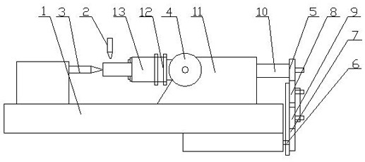
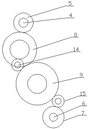
[0021] S1. Build a herringbone groove processing device: such as figure 1 , figure 2 As shown, the herringbone groove processing device includes a workbench 1, a milling cutter 2 and a top 3. The workbench 1 includes a fixed seat 11, a coupling 12 and a work chuck 13. The side end of the fixed seat 11 is connected with an indexing head 4. The tail of the indexing head 4 is connected with the first gear 5, the workbench 1 is connected with the lead screw 6 and the workbench 1 moves longitudinally with the transmission of t...


PUM

PropertyMeasurementUnit
Radiusaaaaaaaaaa

Abstract

The invention relates to a machining process for a herringbone groove of a gear shaft. The machining process comprises the following specific steps: S1, constructing a herringbone groove machining device; S2, positioning the gear shaft: clamping the gear shaft on a working chuck to achieve axial limiting and fixing, clamping the gear shaft through a tip to achieve axial limiting and fixing of the gear shaft, and marking the position, where a herringbone groove is to be machined, of the gear shaft; S3, positioning a milling cutter: starting the milling cutter, and arranging the machining end of the milling cutter at one end point of the to-be-machined herringbone groove; S4, starting a herringbone groove machining device; and S5, discharging of the gear shaft: resetting the tip, taking the gear shaft out of the working chuck, completing herringbone groove machining of the gear shaft, and discharging. The machining process has the following advantages that synchronous linkage of an indexing head and a working head is achieved, the machining precision of a workpiece is improved, the working efficiency is improved, and pits or dents of a herringbone groove are avoided.

Description

Technical field: [0001] The invention relates to the field of gear shaft herringbone groove processing, in particular to a gear shaft herringbone groove processing technology. Background technique: [0002] The processing of the herringbone groove on the CNC milling machine belongs to the processing of the outer peripheral surface of the rotary parts. Considering that the parts are required to have accurate herringbone groove spherical raceway track, it is also necessary to ensure that the herringbone groove spherical raceway has an accurate position when it rotates, and the track of the raceway must be a continuous unobstructed round slideway, and it must be consistent with the raceway axis. The fitting shape is good, so the traditional CNC milling machine and the dividing head are used to process the clamping parts, and the obtained products are difficult to fail to meet the requirements. At present, it is difficult to synchronize the rotary motion of the dividing head wi...

Claims


Application Information

Patent Timeline
IPC IPC(8): B23C3/34B23Q16/02
CPCB23C3/34B23Q16/02
Inventor 潘志进
Owner NANTONG ZHONGLV GEAR CO LTD
Learn More