
Bending device for forming front and back plates of refrigerator

A technology of bending device and front and rear plates, which is applied in the direction of forming tools, metal processing equipment, manufacturing tools, etc., can solve the problems of inability to perform continuous bending, affect work efficiency, and delay time for loading and unloading, so as to improve bending efficiency , to avoid the effect of material jam and continuous bending

Active Publication Date: 2021-06-04
山东三奥制冷设备有限公司
View PDF5 Cites 0 Cited by
  • Summary
  • Abstract
  • Description
  • Claims
  • Application Information

AI Technical Summary

Problems solved by technology

[0003] The front and rear panels of the refrigerator need to be bent during the production process, but the existing bending machine cannot perform continuous bending during the bending process, and the loading and unloading will delay the time and affect the work efficiency. Therefore, a refrigerator is proposed The bending device is used for front and rear plate forming to solve this technical problem

Method used


Image

  • Bending device for forming front and back plates of refrigerator
  • Bending device for forming front and back plates of refrigerator
  • Bending device for forming front and back plates of refrigerator

Examples


Embodiment 1

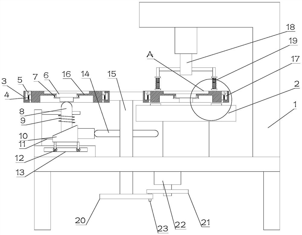
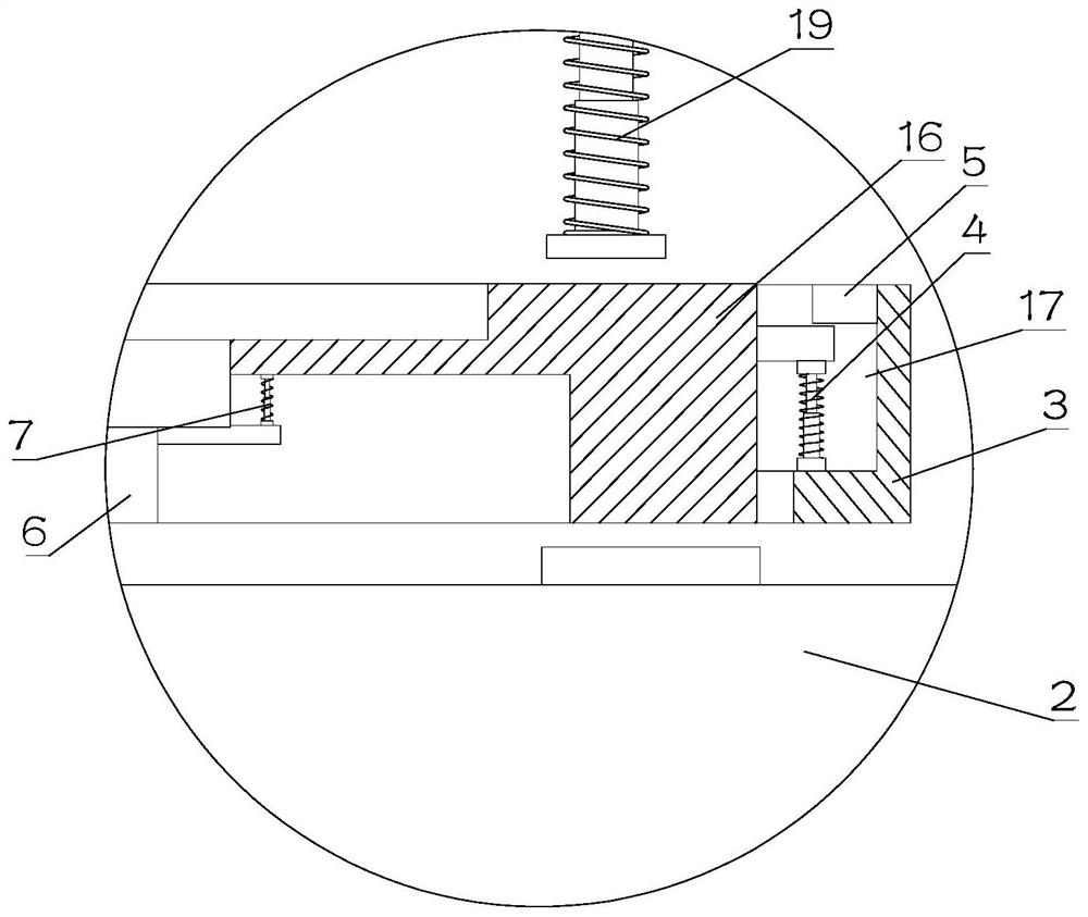
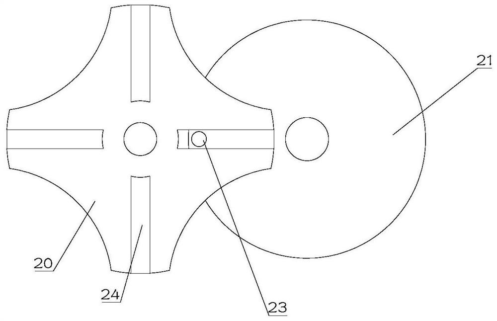
[0024] see Figure 1~3 , in Embodiment 1 of the present invention, a structural diagram of a bending device for forming the front and rear panels of a refrigerator provided in the embodiment of the present invention, including: a device base 1 and a bearing part mounted on the device base 1 in intermittent rotation;

[0025] The carrying part includes an intermittently rotating support shaft 15 and a turntable 3 fixedly mounted on the upper end of the support shaft 15. The turntable 3 is provided with no less than three installation slots 17 in an array, and the interior of the installation slots 17 is elastic. A placement mold 16 is provided; the middle position of the placement mold 16 is provided with an ejector 6, and the ejector 6 is arranged on the through hole at the middle position of the placement mold 16, and the ejector 6 is elastically mounted on the placement mold 16 superior;

[0026] Wherein, the device base 1 is provided with a lifting rod 8, and the supportin...

Embodiment 2

[0030] see Figure 1~3 The main difference between this embodiment 2 and embodiment 1 is that the first elastic support 4 is fixedly installed on both sides of the placement mold 16, and the lower end of the first elastic support 4 is fixedly installed on the installation groove 17. In this way, it is realized that the placement mold 16 is elastically installed in the installation groove 17 .

[0031] In order to prevent the elevating rod 8 from moving upward when the elevating rod 8 is on the ejector part 6, the two sides of the installation groove 17 are also provided with limiting projections 5, which are in contact with the two sides of the placing mold 16. On the edge, thus restricting the upward movement of the placement mold 16.

[0032] As a preferred embodiment of the present invention, the driving mechanism includes a plurality of driving rods 14 arranged on the supporting rotating shaft 15, and the driving rods 14 have the same number as the placement molds 16; the...


PUM


Abstract

The invention relates to the technical field of refrigerator equipment and provides a bending device for forming front and back plates of a refrigerator. The device comprises a device base and a bearing part intermittently and rotatably mounted on the device base, wherein the bearing part comprises a supporting rotating shaft rotating intermittently and a rotating table fixedly mounted at the upper end of the supporting rotating shaft, no less than three mounting slots are formed in an array in the rotating table, and a placing die is elastically arranged in each mounting slot; an ejector piece is arranged in the middle of the placing die, the ejector piece is arranged on a through hole in the middle position of the placing hole, and the ejector piece is elastically mounted on the placing die. The device base is provided with a lifting rod, and the supporting rotating shaft is provided with a driving mechanism for driving the lifting rod to ascend. The device base is further provided with a bending spindle, an elastic pressing plate is further arranged at an output end of the bending spindle, and a supporting table is further arranged on the device base; and the supporting table is arranged right below the bending spindle.

Description

technical field [0001] The invention relates to the technical field of refrigerator equipment, in particular to a bending device for forming front and rear panels of a refrigerator. Background technique [0002] Freezer is another name for refrigerator and freezer. All evaporating tubes of high-quality refrigerators are made of high-quality copper coils and processed into wide-faced special-shaped. The surface of the stainless steel plate is smooth and clean, and the thickness of the whole plate is uniform. The use of an appropriate thickness not only ensures a long service life, but also makes the appearance of the refrigerator smooth and strong. [0003] The front and rear panels of the freezer need to be bent during the production process, but the existing bending machine cannot perform continuous bending during the bending process, and the loading and unloading will delay the time and affect the work efficiency. Therefore, a freezer is proposed Bending device is used f...

Claims


Application Information

Patent Timeline
Patent Type & Authority Applications(China)
IPC IPC(8): B21D11/10B21D11/22B21D37/06B21D37/10B21D45/04
CPCB21D11/10B21D11/22B21D37/06B21D37/10B21D45/04Y02P40/57
Inventor 吴赵平
Owner 山东三奥制冷设备有限公司
Learn More