Constant-pressure pressurizing device and automatic rolling machine with same

A pressurizing device and kneading machine technology, applied in the direction of fluid pressure control, non-electric variable control, sustainable manufacturing/processing, etc., can solve the problems of unfavorable saving of preparation costs, affecting kneading efficiency, long kneading time, etc., and achieve the goal of feeding The effect of increasing the volume, improving the kneading efficiency and reducing the kneading time

Active Publication Date: 2021-06-04
湖北华宜智能科技有限公司
View PDF6 Cites 0 Cited by
  • Summary
  • Abstract
  • Description
  • Claims
  • Application Information

AI Technical Summary

Problems solved by technology

The feeding structure is designed on the side of the grinding body, and the rotation of the grinding body drives the tea leaves into the grinding body. The disadvantage of the existing technology is that the feeding amount is small, and it can only be gradually transferred through the connecting rod or the brush on the connecting rod. The tea is swept into the rolling table, and then the tea basket is put into the grinding body through the rotation of the grinding body. This feeding structure affects the rolling efficiency, and the rolling time is long, which is not conducive to saving the preparation cost.

Method used


Image

  • Constant-pressure pressurizing device and automatic rolling machine with same
  • Constant-pressure pressurizing device and automatic rolling machine with same
  • Constant-pressure pressurizing device and automatic rolling machine with same

Examples


Embodiment Construction

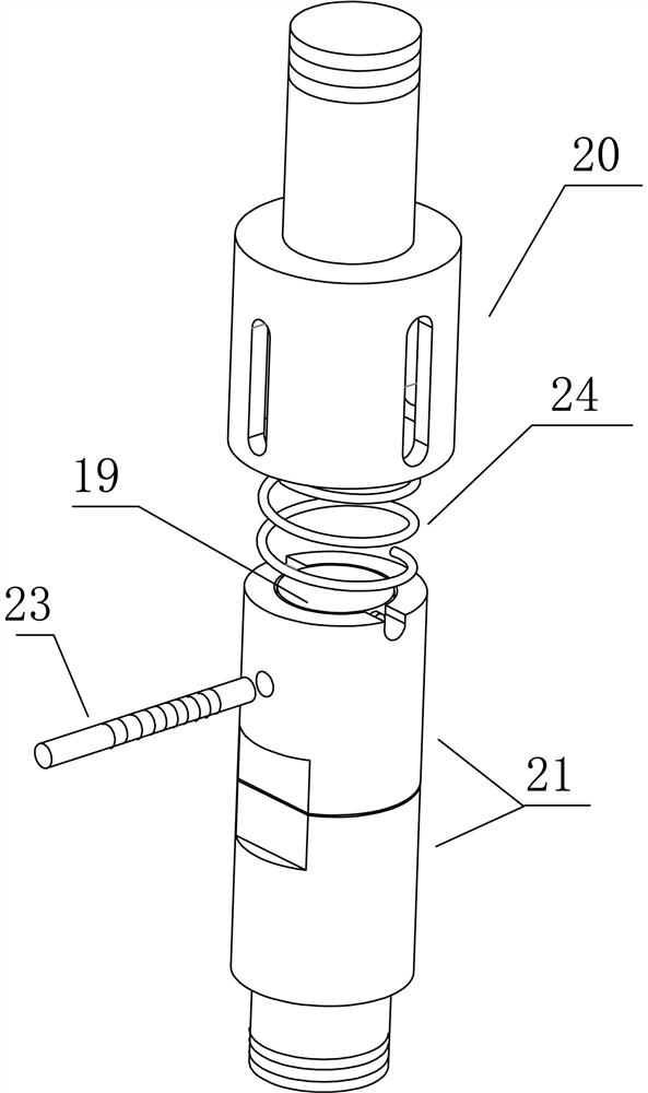
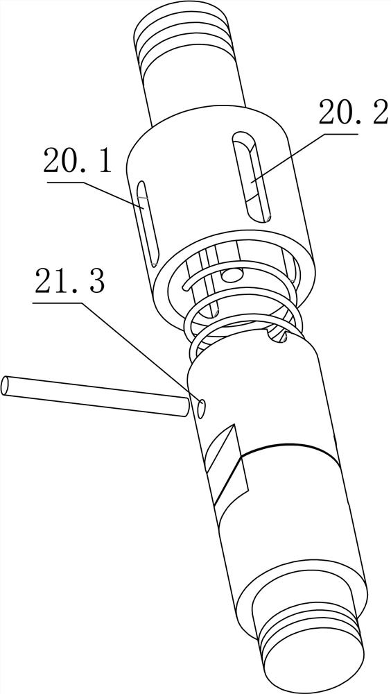
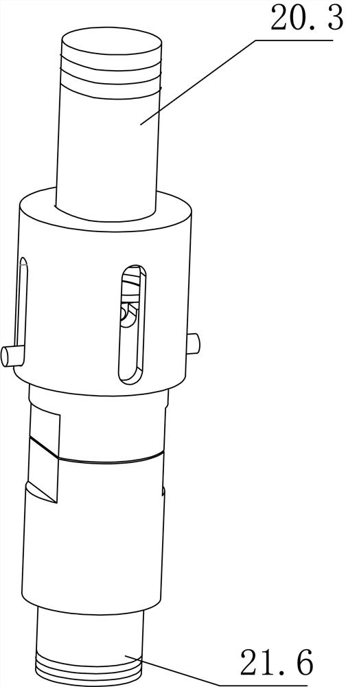
[0038] The preferred solution is as Figure 1 to Figure 6 As shown, a constant pressure pressurizing device includes a pressure sensor 19, the pressure sensor 19 is installed between the upper connecting part 20 and the lower connecting part 21, and the upper connecting part 20 and the lower connecting part 21 are slidably connected, The upper connecting piece 20 is driven to move up and down by the gland lifting device 22, and the lower connecting piece 21 is used for connecting with the gland.

[0039]The gland lifting device 22 is preferably an electric push rod, and its model can be an XTL100 DC electric push rod. The motor of the electric push rod is a servo motor, and the servo controller is the main control device of this machine solution. The pressure sensor 19 can be a button-type pressure sensor. The pressure sensor 19 converts the pressure signal into an analog signal of 4-20mA. The servo controller controls the action of the electric push rod according to the analo...


PUM


Abstract

The invention discloses a constant-pressure pressurizing device and an automatic rolling machine with the constant-pressure pressurizing device. The constant-pressure pressurizing device comprise a pressure sensor, the pressure sensor is arranged between an upper connecting piece and a lower connecting piece, the upper connecting piece and the lower connecting piece are connected in a sliding mode, the upper connecting piece is driven by a gland lifting device to move up and down, the lower connecting piece is used for being connected with a gland, the lower connecting piece comprises a column body, a pressure sensor placement groove is formed in the top of the column body, the pressure sensor placement groove is internally used for placing the pressure sensor, a positioning pin is arranged on the side wall of the column body, the upper connecting piece comprises an inserting cylinder, a positioning sliding groove is formed in the side wall of the inserting cylinder, the inserting cylinder is used for being connected to the column body in a sleeving mode, and the positioning pin is slidably connected with the positioning sliding groove. According to the constant-pressure pressurizing device and the automatic rolling machine, the pressure of the gland can be adjusted within a fixed value, so that the pressure on tea leaves in a mill body is kept fixed, and the tea leaf rolling quality is advantageously improved.

Description

technical field [0001] The invention belongs to the field of tea processing equipment, in particular to a constant pressure pressurizing device and an automatic rolling machine with the constant pressure pressurizing device. Background technique [0002] At present, the equipment used to make tea is becoming more and more intelligent. For example, automatic rolling machines replace manual rolling, which improves rolling efficiency and saves labor costs. Chinese patent document CN 110651855 A discloses "a kind of automatic tea processing system", the automatic rolling machine disclosed in this document is as Figure 13 shown. The kneading machine includes a kneading table 52, a cover body 53 (equivalent to a blanking door), a fixed rod 531, a pneumatic cylinder 532, a limit rod 533, a rotating rod 54, a connecting rod 56, a fixed ring 57, a grinding body 58, a gland 581, screw rod 582, connecting body 583, bevel gear disc 584, the fourth speed regulating motor 585 and variab...

Claims


Application Information

Patent Timeline
Patent Type & Authority Applications(China)
IPC IPC(8): A23F3/12G05D16/20
CPCA23F3/12Y02P70/50
Inventor 黄孝波
Owner 湖北华宜智能科技有限公司
Why Eureka
Try Eureka