
Blue film chip ejection device

A technology for ejecting devices and chips, which is applied in the direction of electrical components, semiconductor/solid-state device manufacturing, circuits, etc., can solve problems such as broken vacuum, inconsistent degree of tightness, chip damage, etc., to achieve the effect of ensuring stability and not being damaged

Pending Publication Date: 2021-06-01
CHENGDU TSUHAN SCI & TECH
View PDF0 Cites 1 Cited by
  • Summary
  • Abstract
  • Description
  • Claims
  • Application Information

AI Technical Summary

Problems solved by technology

[0004] 1. When using the cam 3 for jacking, to eject the chip and suck the chip away by the chip suction head, the ejector pin 1 and the chip suction head must clamp the chip to move up synchronously. If the speed of the ejector pin 1 is greater than the speed of the chip suction head, the chip will 1 is very easy to be crushed. If the speed of thimble 1 is lower than the speed of the chip suction head, the chip is difficult to be sucked successfully due to the viscosity of the blue film. It is very cumbersome to adjust the speed and the speed of the chip tip to be consistent
[0005] 2. The degree of tightness of the blue film is inconsistent during the crystal expansion process. When the blue film is loose, the vacuum cover 2 of this device cannot be adjusted up and down. When the vacuum cover 2 moves left and right, it will collide with the side of the chip on the blue film. The next chip pickup will fail and there is a risk of chip damage
[0006] 3. This device can only realize the ejection of ejector pin 1, and the chip is sucked in a way that the chip does not move. In actual use, because the moment the chip is ejected by ejector pin 1, the upward movement of the chip suction head lags behind the ejector pin, so there is a problem that the chip is ejected. The risk of chipping, if the chip suction head moves before the ejector pin 1 ejects the chip, it will break the vacuum, and there is a risk of chip suction failure

Method used


Image

  • Blue film chip ejection device
  • Blue film chip ejection device
  • Blue film chip ejection device

Examples


Embodiment Construction

[0033] The implementation of the present invention will be illustrated by specific specific examples below, and those skilled in the art can easily understand other advantages and effects of the present invention from the contents disclosed in this specification.

[0034] see Figure 3 to Figure 8 . It should be noted that the structures, proportions, sizes, etc. shown in the drawings attached to this specification are only used to match the content disclosed in the specification, for those who are familiar with this technology to understand and read, and are not used to limit the implementation of the present invention. Limiting conditions, so there is no technical substantive meaning, any modification of structure, change of proportional relationship or adjustment of size, without affecting the effect and purpose of the present invention, should still fall within the scope of the present invention. The disclosed technical content must be within the scope covered. At the sa...


PUM


Abstract

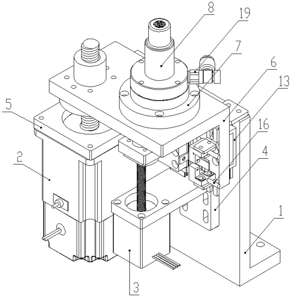
A blue film chip ejection device belongs to the technical field of chip assembly and comprises a mounting bottom plate, wherein a vacuum cover lifting plate capable of moving up and down is mounted on the mounting bottom plate, a vacuum cover is arranged on the vacuum cover lifting plate, an ejector pin is arranged at the top part of the vacuum cover, a vacuum cover lifting lead screw motor for driving the vacuum cover lifting plate to move up and down is further installed on the installation bottom plate, an ejector pin lifting lead screw motor for driving the ejector pin to move up and down is further installed on the installation bottom plate, the ejector pin is inserted into an ejector pin lifting rod, the ejector pin lifting rod is installed on an ejector pin installation plate, and a screw rod of the ejector pin lifting screw rod motor penetrates through the ejector rod mounting plate and then is connected through a nut. According to the blue film chip ejection device, the vacuum cover sucks a blue film and pulls down to drive a chip to move down to contact the ejector pin to eject the chip, and the vacuum cover sucks the blue film around the chip and pulls down to separate the chip from the blue film, so that the risk of crushing the chip is eliminated, and meanwhile, the risk of chip damage caused by overshoot due to the fact that the chip suction nozzle lags behind the ejector pin at the moment when the ejector pin ejects the chip is further eliminated.

Description

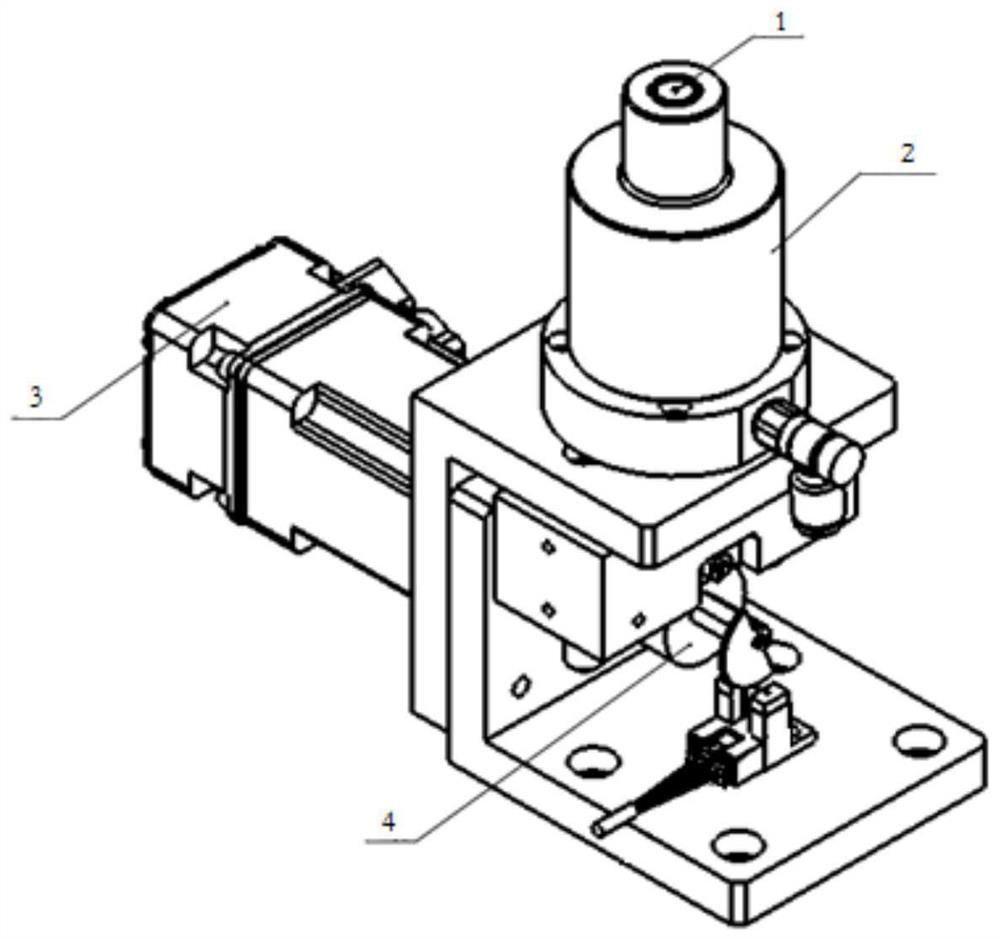
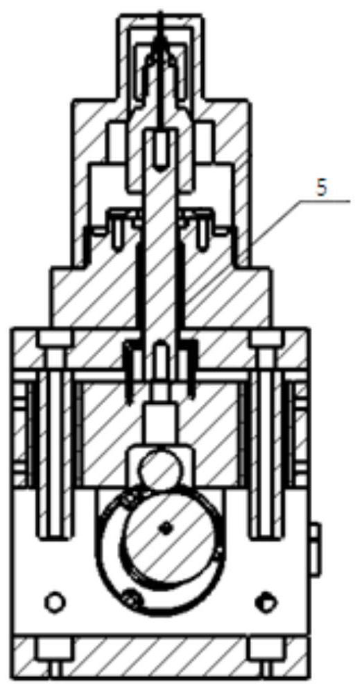
technical field [0001] The invention belongs to the technical field of chip assembly, and relates to a chip stripping device, in particular to a blue film chip ejecting device. Background technique [0002] At present, the ejection device of the blue film chip is mainly driven by the motor 3 to rotate the cam 4, and the cam 3 drives the shaft connected to the thimble 1 through the ball bushing assembly 5, so that the thimble 1 moves up and down to pierce the blue film disc and eject the chip, as figure 1 and figure 2 . [0003] Although the traditional blue-film chip ejection device can realize chip ejection, it has the following disadvantages in actual use: [0004] 1. When using the cam 3 for jacking, to eject the chip and suck the chip away by the chip suction head, the ejector pin 1 and the chip suction head must clamp the chip to move up synchronously. If the speed of the ejector pin 1 is greater than the speed of the chip suction head, the chip will 1 is very easy ...

Claims


Application Information

Patent Timeline
IPC IPC(8): H01L21/683
CPCH01L21/6838
Inventor 夏阳
Owner CHENGDU TSUHAN SCI & TECH
Learn More