
Optical image rotation eliminating mechanism of periscopic panoramic sighting telescope

A sight and periscope technology, which is applied in the field of optical anti-rotation mechanism of periscope sight, can solve problems such as complex structure of gear transmission group, influence on system image stabilization accuracy, uneven gear rotation, etc. Lightweight, simple assembly and adjustment process, smooth rotation effect

Pending Publication Date: 2021-06-01
西安应用光学研究所
View PDF2 Cites 1 Cited by
  • Summary
  • Abstract
  • Description
  • Claims
  • Application Information

AI Technical Summary

Problems solved by technology

On the one hand, due to the transmission error of the gear set and the machining error, the image rotation error will be caused; on the other hand, the clearance and transmission efficiency of the gear transmission will affect its transmission accuracy. Adjusting and reducing the clearance of the gear set will easily cause the gear to rotate unsmoothly. The friction torque is increased, which in turn interferes with the stability of the turntable, thereby affecting the image stabilization accuracy of the entire system; moreover, the structure of the gear transmission group is relatively complicated, difficult to install and adjust, and high manufacturing cost

Method used


Image

  • Optical image rotation eliminating mechanism of periscopic panoramic sighting telescope
  • Optical image rotation eliminating mechanism of periscopic panoramic sighting telescope
  • Optical image rotation eliminating mechanism of periscopic panoramic sighting telescope

Examples


Embodiment Construction

[0028] In order to make the purpose, content and advantages of the present invention clearer, the specific implementation manners of the present invention will be further described in detail below in conjunction with the accompanying drawings and embodiments.

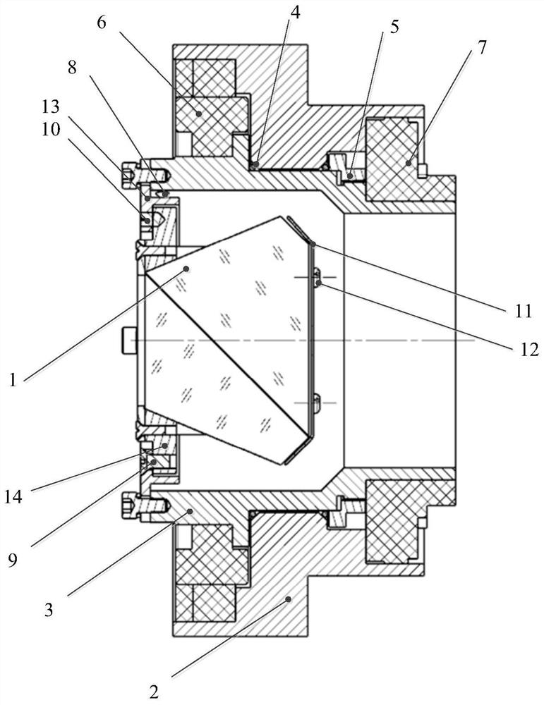
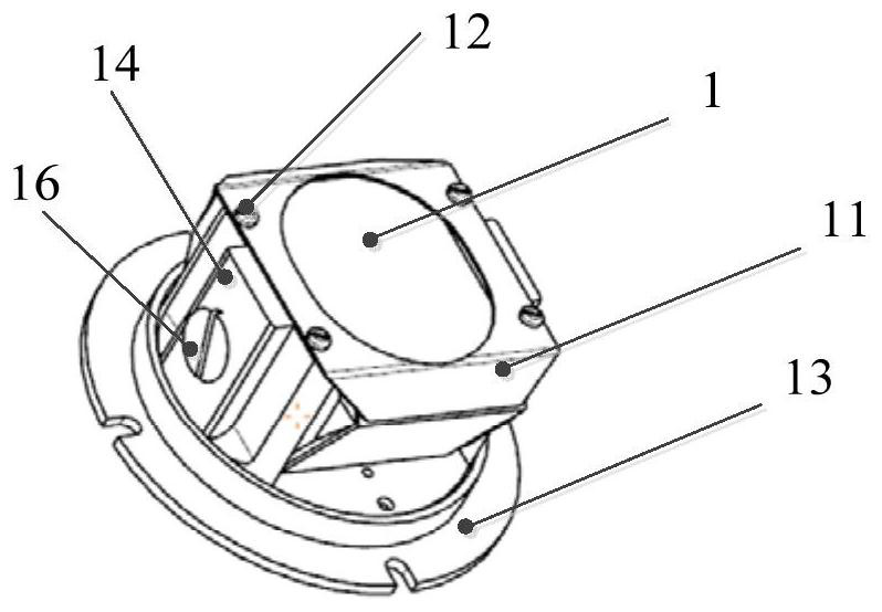
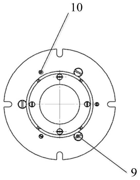
[0029] like figure 1 As shown, the periscope-type periscope sight optical derotation mechanism of the present invention includes: a prism rotary shaft system, a Behan prism assembly, a DC torque motor 6 and a photoelectric encoder 7; the prism rotary shaft system includes a base 2 and a coaxial Installed on the rotating shaft 3 inside the base 2, the Bechan prism assembly is installed on the rotating shaft 3; the DC torque motor 6 and the photoelectric encoder 7 are respectively placed at both ends of the shaft system, the DC torque motor 6 is located at the front end of the shaft system, and the photoelectric encoder 7 Located at the rear end of the shaft system, the two stators are fixedly installed on the base 2 resp...


PUM


Abstract

The invention discloses an optical image rotation eliminating mechanism of a periscopic panoramic sighting telescope. The optical image rotation eliminating mechanism comprises a prism rotating shaft system, a Pechan prism assembly, a direct-current torque motor and a photoelectric encoder. The prism rotating shaft system comprises a base and a rotating shaft coaxially mounted in the base, and the Pechan prism assembly is mounted on the rotating shaft; the direct-current torque motor and the photoelectric encoder are arranged at the two ends of the shafting respectively, the direct-current torque motor is located at the front end of the shafting, the photoelectric encoder is located at the rear end of the shafting, stators of the direct-current torque motor and the photoelectric encoder are fixedly installed on the base respectively, rotors and the rotating shaft are coaxially installed, the direct-current torque motor is used for driving the Pechan prism assembly rotating shaft system to rotate, the photoelectric encoder is used for real-time angle measurement and position feedback, and the image rotation eliminating function is achieved. The mechanism is simple in structure, low in manufacturing cost, convenient to install and adjust and high in imaging precision, and the problem of image rotation in the 360-degree panoramic sighting process of the periscopic panoramic sighting telescope is solved.

Description

technical field [0001] The invention belongs to the technical fields of optics and precision machinery, and relates to an optical derotation mechanism of a periscope-type periscope sight. Background technique [0002] At present, most of the peripheral sights use periscope optical systems, and there is an image rotation problem when the observation field scans with the azimuth rotation axis during the 360° peripheral sighting process. To solve this problem, the optical derotation method is usually adopted, that is, a derotation prism is installed in the optical path of the system based on the micro-rotation theorem of the reflective prism, and the derotation effect is achieved by the rotation of the derotation prism. Therefore, it is necessary to design a derotation mechanism to realize the rotation of the derotation prism. [0003] At present, the following methods are mainly used for de-image rotation: optical de-image-rotation, physical de-image-rotation, electronic de-i...

Claims


Application Information

Patent Timeline
Patent Type & Authority Applications(China)
IPC IPC(8): G02B23/08G02B7/18
CPCG02B23/08G02B7/1805
Inventor 刘张飞郭新胜郭渝琳寿少峻张兰兰冯颖张芳郑凤翥张衡
Owner 西安应用光学研究所
Learn More