
A machine tool visual positioning method and system, and machine tool

A technology for visual positioning and machine tools, applied in the field of CNC machine tools, can solve the problems of inflexible use, unsuitable promotion and use, etc., and achieve the effects of easy and fast finding, wide applicability, and strong practicability

Active Publication Date: 2019-01-25
SYMG SHANGHAI INTELLIGENCE SYST CO LTD
View PDF5 Cites 0 Cited by
  • Summary
  • Abstract
  • Description
  • Claims
  • Application Information

AI Technical Summary

Problems solved by technology

However, the current visual positioning based on edge features mostly uses straight lines and circles to locate the target. Before positioning, it is necessary to manually specify which lines and circles are used to calculate the target position within what range and in what way. Professionals are required to formulate the positioning. rules, resulting in inflexible use and not suitable for widespread use

Method used


Image

  • A machine tool visual positioning method and system, and machine tool
  • A machine tool visual positioning method and system, and machine tool
  • A machine tool visual positioning method and system, and machine tool

Examples


Embodiment Construction

[0068] Embodiments of the present invention are described below through specific examples, and those skilled in the art can easily understand other advantages and effects of the present invention from the content disclosed in this specification. The present invention can also be implemented or applied through other different specific implementation modes, and various modifications or changes can be made to the details in this specification based on different viewpoints and applications without departing from the spirit of the present invention. It should be noted that, in the case of no conflict, the following embodiments and features in the embodiments can be combined with each other.

[0069] It should be noted that the diagrams provided in the following embodiments are only schematically illustrating the basic ideas of the present invention, and only the components related to the present invention are shown in the diagrams rather than the number, shape and shape of the compo...


PUM


Abstract

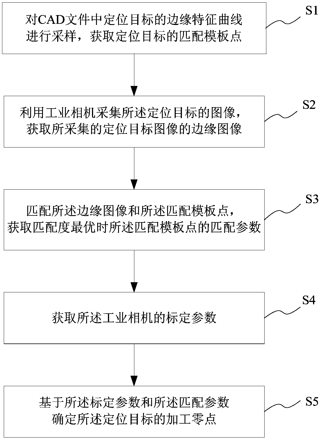
The invention provides a machine tool vision positioning method and system and a machine tool. The method includes the following steps: sampling the edge characteristic curve of a positioning target in a CAD file, and obtaining a matching template point of the positioning target; collecting an image of the positioning target by using an industrial camera, and obtaining an edge image of the collected positioning target image; matching the edge image with the matching template point, and obtaining the matching parameters of the matching template point when the matching degree is optimal; obtaining the calibration parameters of the industrial camera; and determining the machining zero of the positioning target based on the calibration parameters and the matching parameters. According to the machine tool vision positioning method and system and the machine tool, the shaped drawn by CAD is used as the characteristic of edge positioning, automatic positioning of a work piece positioned in anon-tooling way can be realized, the machining zero can be obtained and the actual size of the positioning target can be measured, and therefore, the positioning efficiency and machining efficiency ofwork pieces can be improved.

Description

technical field [0001] The invention relates to the technical field of a numerically controlled machine tool, in particular to a machine tool visual positioning method and system, and a machine tool. Background technique [0002] In the prior art, visual positioning basically includes the following two methods: [0003] (1) Visual positioning based on image grayscale template matching [0004] Specifically, the visual positioning method based on image grayscale template matching first needs to set a template of the target image, which is usually a screenshot obtained by taking pictures of the target in the actual environment; Calculate the real-time position of the target to complete the positioning. This method is relatively common in practical applications due to its simple implementation. However, it requires a stable lighting environment and a small range of target changes. Otherwise, when there is a large difference between the image captured immediately and the tem...

Claims


Application Information

Patent Timeline
Patent Type & Authority Patents(China)
IPC IPC(8): G05B19/4097
CPCG05B19/4097G05B2219/32153Y02P90/02
Inventor 朱志浩陈阁周扬
Owner SYMG SHANGHAI INTELLIGENCE SYST CO LTD
Learn More