Tunnel concrete pouring device and using method

A concrete and tunnel technology, which is applied in tunnels, tunnel linings, mining equipment, etc., can solve the problems of noise reduction and prevention, complex structure, friction reduction, etc., and achieve the effect of reducing noise, solving low efficiency and reducing friction

Active Publication Date: 2021-06-01
CHINA RAILWAY NO 9 GRP 2ND ENG
View PDF6 Cites 0 Cited by
  • Summary
  • Abstract
  • Description
  • Claims
  • Application Information

AI Technical Summary

Problems solved by technology

[0003] In view of the above situation, in order to overcome the defects of the prior art, the present invention provides a tunnel concrete pouring equipment and its use method. The Leidenfrost effect is creatively applied in the present invention, and a water vapor film is formed by evaporating a liquid on the surface of a high-temperature object. , reduce the frictional force generated by the direct contact between the concrete and the pouring mold, realize the function of facilitating the movement of the pouring mold, creatively apply the Huygens principle in the present invention, use the principle of porous arc-shaped dielectric material to absorb sound, and reduce the transportation time of transport vehicles The huge noise generated during the time can realize the function of reducing the noise and preventing the gravel from falling and hurting the staff below. The temperature and humidity sensor is used to monitor the humidity of the cement wall, calculate the degree of cement solidification, and prevent the cement wall from collapsing due to unsolidification. The principle of surface effect The creative application in the present invention utilizes the air film generated at the bottom of the pouring equipment to properly raise the base to reduce the pressure of the pouring equipment on the guide rails and ensure the contact area between the rollers and the engaging grooves to increase the moving speed of the pouring equipment. function, which effectively solves the problems of low efficiency, complex structure and inconvenient maintenance of existing tunnel concrete pouring equipment on the market

Method used


Image

  • Tunnel concrete pouring device and using method
  • Tunnel concrete pouring device and using method
  • Tunnel concrete pouring device and using method

Examples


Embodiment Construction

[0036] The technical solutions in the embodiments of the present invention will be clearly and completely described below in conjunction with the accompanying drawings in the embodiments of the present invention. Obviously, the described embodiments are only some of the embodiments of the present invention, not all of them; based on The embodiments of the present invention and all other embodiments obtained by persons of ordinary skill in the art without making creative efforts belong to the protection scope of the present invention.

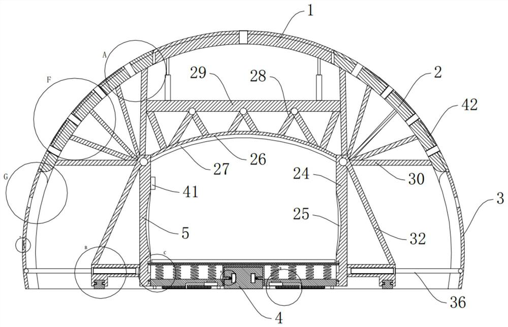
[0037] Such as Figure 1-13 As shown, a tunnel concrete pouring equipment of the present invention includes an upper pouring device 1, a sidewall pouring device 2, a bottom pouring device 3, a base pushing device 4 and a noise reduction support device 5, and the bottom pouring device 3 is connected to the base The push device 4 is connected, the side wall pouring device 2 is connected with the bottom pouring device 3, the upper end pouring devic...


PUM


Abstract

The invention discloses a tunnel concrete pouring device and a using method. The tunnel concrete pouring device comprises an upper end pouring device, a side wall pouring device, a bottom end pouring device, a base pushing device and a noise reduction supporting device. The invention belongs to the technical field of tunnel concrete pouring devices, and particularly relates to the tunnel concrete pouring device and the using method. The Leidenfrost effect is creatively applied to the tunnel concrete pouring device, friction force generated by direct contact between concrete and a pouring mold is reduced, the Huygens principle is creatively applied to the tunnel concrete pouring device, and huge noise generated during transportation of a transport vehicle is reduced; the humidity of a cement wall is monitored through a temperature and humidity sensor, and the situation that the cement wall collapses due to the fact that the cement wall is not solidified is avoided; and the surface effect principle is creatively applied to the tunnel concrete pouring device, a base is properly lifted to weaken the pressure of the pouring device on a guide rail, and the problems that an existing tunnel concrete pouring device on the current market is low in efficiency, complex in structure and inconvenient to maintain are effectively solved.

Description

technical field [0001] The invention belongs to the technical field of tunnel concrete pouring devices, and specifically refers to a tunnel concrete pouring equipment and a use method. Background technique [0002] At present, with the rapid development of high-speed rail in my country, there are more and more tunnels; with the continuous improvement of tunnel lining quality and standardized construction requirements, the quality requirements of tunnel lining concrete are getting higher and higher. During the pouring process of traditional tunnels, due to the backlog of concrete at the lower end, the gap between the concrete and the pouring device is reduced, and the friction between the equipment and the concrete tunnel wall is increased, which seriously affects the work efficiency of the pouring equipment moving to the next pouring point. In addition, during the process of transporting concrete by the concrete transport vehicle, the noise and vibration generated by the tra...

Claims


Application Information

Patent Timeline
Patent Type & Authority Applications(China)
IPC IPC(8): E21D11/10E21D11/38
CPCE21D11/102E21D11/38E21D11/105
Inventor 佟运辉王拥军王文超孙文志李海涛王景华杨跃飞杨志才郭祥斌邹宇郭景生张明洲敖日格乐巴图鞠光蒋士全王宝健张成建
Owner CHINA RAILWAY NO 9 GRP 2ND ENG
Why Eureka
Try Eureka