Clean energy bioenergy reaction device and use method thereof

A technology of reaction device and clean energy, applied in biochemical cleaning devices, biochemical equipment and methods, enzymology/microbiology devices, etc., can solve the problems of inability to stack straws, reduce the efficiency of biogas preparation, and low efficiency of straw fermentation and decomposition, etc. , to achieve the effect of increasing sealing effect, improving efficiency and improving transmission efficiency

Pending Publication Date: 2021-06-01
王晓丽
View PDF0 Cites 1 Cited by
  • Summary
  • Abstract
  • Description
  • Claims
  • Application Information

AI Technical Summary

Problems solved by technology

[0003] At present, for the utilization of biomass energy in straw, the straw is generally directly crushed and broken into a closed anaerobic environment, and under certain conditions of temperature, humidity and pH, it is fermented and decomposed to form biogas for people to use as basic fuel. Currently, when straw is put into the sedimentation equipment for fermentation and decomposition, the crushed straw is usually poured directly from the feed port of the sedimentation equipment, and this feeding method will make all the straws poured into piles. In the local position of the inner cavity of the sedimentation equipment, the straw cannot be stacked in other positions in the inner cavity of the sedimentation equipment, resulting in uneven distribution of the straw in the sedimentation equipment, which not only causes the utilization rate of the inner cavity of the sedimentation equipment, but also accumulates all in one place. The efficiency of straw fermentation and decomposition is low, which reduces the efficiency of biogas production

Method used


Image

  • Clean energy bioenergy reaction device and use method thereof
  • Clean energy bioenergy reaction device and use method thereof
  • Clean energy bioenergy reaction device and use method thereof

Examples


Embodiment Construction

[0038] The following will clearly and completely describe the technical solutions in the embodiments of the present invention with reference to the accompanying drawings in the embodiments of the present invention. Obviously, the described embodiments are only some, not all, embodiments of the present invention. Based on the embodiments of the present invention, all other embodiments obtained by persons of ordinary skill in the art without making creative efforts belong to the protection scope of the present invention.

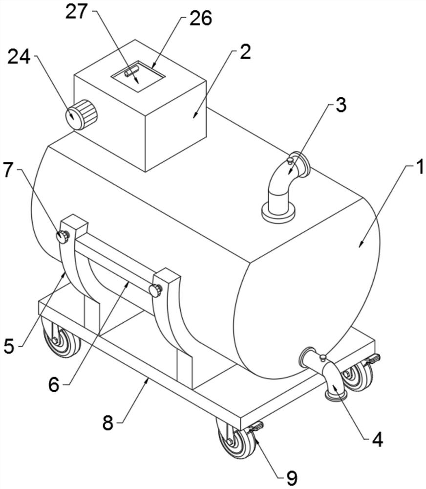
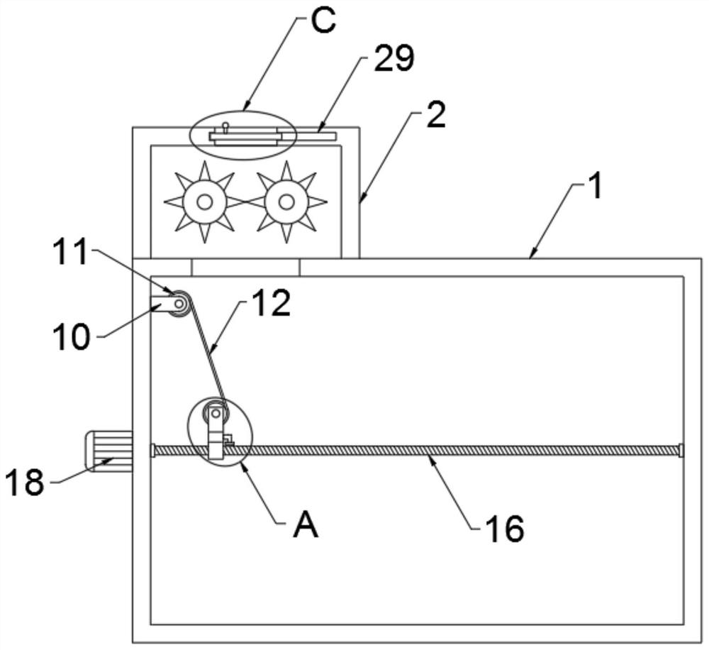
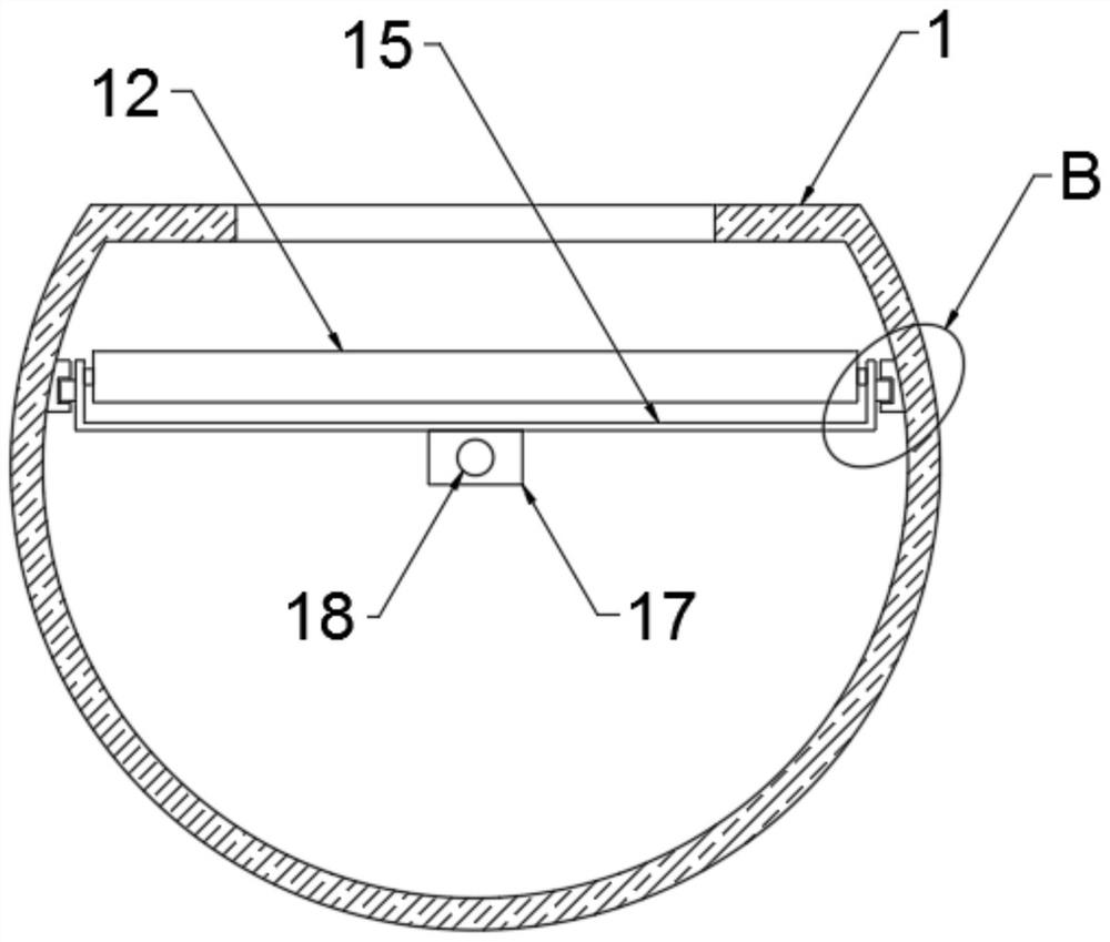
[0039] The present invention provides such Figure 1-9 A clean energy bioenergy reaction device shown includes:

[0040]Settling box 1, the top of the settling box 1 is flat, which is convenient for the installation of the feeding mechanism and other components. The outer wall of the settling box 1 is arc-shaped, which is convenient for the distribution and discharge of debris. The exhaust pipe 3 is fixed and inserted in the settling box 1, the discharge pipe...


PUM


Abstract

The invention discloses a clean energy bioenergy reaction device and a using method thereof. The clean energy bioenergy reaction device comprises a settling tank, an exhaust pipe, a discharging pipe, a feeding mechanism, a supporting mechanism and a material guiding mechanism, the material guiding mechanism is a first concave fixing plate, an inner cavity of the first concave fixing plate is rotationally connected with a connecting rod, and the outer wall of the connecting rod is movably sleeved with a material guiding strip plate; spring strips are fixedly connected to the two sides of the bottom end of the material guide strip plate, a reciprocating translation mechanism is arranged in an inner cavity of the sediment box, a second concave fixing plate is arranged above the reciprocating translation mechanism in a transmission mode, a winding rod is rotationally connected to an inner cavity of the second concave fixing plate, and the other end of the material guide strip plate is wound on the outer wall of the winding rod. The reciprocating translation mechanism in the settling tank is used for driving the second concave fixing plate to translate in a reciprocating manner, and the first concave fixing plate and the connecting rod are matched for use, so that crushed straw can uniformly fall in the settling tank, and the biogas preparation efficiency is improved.

Description

technical field [0001] The invention relates to the field of clean energy, in particular to a clean energy bioenergy reaction device and a use method thereof. Background technique [0002] Bioenergy is a kind of clean energy. It is an energy form in which solar energy is stored in organisms in the form of chemical energy. It is an energy with biomass as a carrier. It directly or indirectly comes from the photosynthesis of plants. Among the renewable energy sources, biomass is unique. It is the stored solar energy and the only renewable carbon source that can be converted into conventional solid, liquid and gaseous fuels. Sorghum straw is the main biomass energy. Withered plants such as straw are used to ferment and decompose to form biogas for people to use as fuel. [0003] At present, for the utilization of biomass energy in straw, the straw is generally directly crushed and broken into a closed anaerobic environment, and under certain conditions of temperature, humidity ...

Claims


Application Information

Patent Timeline
IPC IPC(8): C12M1/107C12M1/33C12M1/00
CPCC12M21/04C12M23/46C12M23/48C12M23/50C12M23/52C12M29/20C12M33/22C12M37/04C12M45/02
Inventor 王晓丽
Owner 王晓丽
Why Eureka
Try Eureka