Hole milling device for machining automobile crankshaft

A crankshaft machining and hole milling technology, applied in positioning devices, metal machining equipment, metal machining mechanical parts, etc., can solve the problem of inability to move the car crankshaft to ensure the quality and accuracy of the car crankshaft milling hole, the car crankshaft is easy to move and rotate, and the milling Hole quality and precision reduction and other problems, to achieve the effect of benefiting the quality of milling holes, improving the efficiency of milling holes, and improving stability

Active Publication Date: 2021-06-01
山西东鑫衡隆机械制造股份有限公司
View PDF9 Cites 2 Cited by
  • Summary
  • Abstract
  • Description
  • Claims
  • Application Information

AI Technical Summary

Problems solved by technology

[0002] In the process of milling the car crankshaft, the car crankshaft needs to be completely fixed, and the car crankshaft cannot be moved to ensure the quality and accuracy of the car crankshaft milling hole. Due to the structural characteristics of the car crankshaft, it is difficult to fix the car crankshaft. Moreover, in the process of milling holes on the crankshaft of the automobile at a position not on the center line, the crankshaft of the automobile is easy to move and rotate, resulting in a reduction in the quality and accuracy of the milled holes. The crankshaft itself causes damage, but the existing milling device for automobile crankshaft processing cannot solve the above problems, and the existing milling device for automobile crankshaft processing does not have the function of automatic alignment, and the processing efficiency can be further improved. For this reason, the present invention proposes a kind of milling device for automobile crankshaft machining

Method used


Image

  • Hole milling device for machining automobile crankshaft
  • Hole milling device for machining automobile crankshaft
  • Hole milling device for machining automobile crankshaft

Examples


Embodiment approach

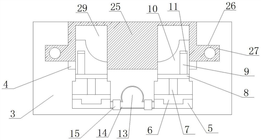
[0027] As a preferred embodiment of the present invention, the number of hexagonal limit rods 9 on the top of the top plate 8 is 2, the number of movable clamping seats 25 is 2, and the bearing seat 10 passes through the hexagonal connecting groove 11 Cooperating with the hexagonal limit rod 9 and connecting with the top plate 8, it is very convenient to disassemble the bearing seat 10 for replacement and has strong stability, will not shake during use, and ensures the quality of the milled hole.

[0028] As a preferred embodiment of the present invention, both the pressurization channel 16 and the oil supply pipeline 13 are filled with hydraulic oil.

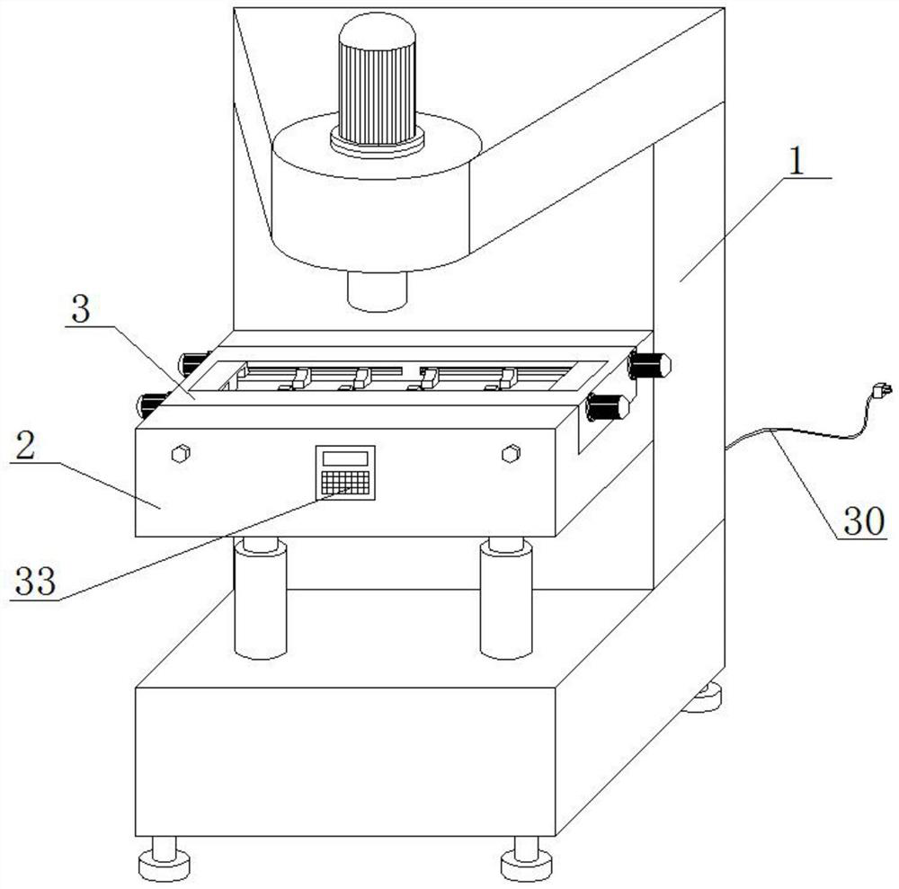
[0029] As a preferred embodiment of the present invention, the workbench 2 is fixedly installed on the milling machine 1, and the special-shaped clamping and fixing seat 3 is embedded on the workbench 2 and fixed by bolts.

[0030] As a preferred embodiment of the present invention, a control panel 33 is installed on the front ...


PUM


Abstract

The invention provides a hole milling device for machining an automobile crankshaft. The hole milling device comprises a milling machine, a workbench and a special-shaped clamping and fixing seat, a strip-shaped clamping groove is formed in the top of the special-shaped clamping and fixing seat, a plurality of telescopic grooves are formed in the inner side wall of the bottom of the strip-shaped clamping groove, and a convex movable seat is movably installed in the bottom of each telescopic groove. The hole milling device for machining the automobile crankshaft is reasonable in design, a plurality of telescopic bearing seats are installed in the strip-shaped clamping groove, arc-shaped attaching grooves are formed in the tops of the bearing seats, the arc-shaped attaching grooves of the plurality of bearing seats can be completely attached to all parts of the automobile crankshaft, when the automobile crankshaft is correspondingly placed on all the bearing seats, under the limiting effect of the arc-shaped attaching grooves, the position of the automobile crankshaft can be automatically corrected, the hole milling efficiency of the automobile crankshaft can be effectively improved, the stability of the automobile crankshaft can be improved, the automobile crankshaft is prevented from moving, and the hole milling quality can be improved.

Description

technical field [0001] The invention belongs to the technical field of automobile crankshaft processing equipment, in particular to a milling device for automobile crankshaft processing. Background technique [0002] In the process of milling the car crankshaft, the car crankshaft needs to be completely fixed, and the car crankshaft cannot be moved to ensure the quality and accuracy of the car crankshaft milling hole. Due to the structural characteristics of the car crankshaft, it is difficult to fix the car crankshaft. Moreover, in the process of milling holes on the crankshaft of the automobile at a position not on the center line, the crankshaft of the automobile is easy to move and rotate, resulting in a reduction in the quality and accuracy of the milled holes. The crankshaft itself causes damage, but the existing milling device for automobile crankshaft processing cannot solve the above problems, and the existing milling device for automobile crankshaft processing does...

Claims


Application Information

Patent Timeline
Patent Type & Authority Applications(China)
IPC IPC(8): B23C3/00B23Q3/08B23Q11/00
CPCB23C3/00B23Q3/064B23Q3/082B23Q11/0032B23C2215/08
Inventor 陈萍
Owner 山西东鑫衡隆机械制造股份有限公司
Why Eureka
Try Eureka