A diode-clamped back-to-back bridgeless three-level rectifier

A three-level rectification, diode technology, applied in electrical components, AC power input into DC power output, output power conversion devices and other directions, can solve problems such as increased power loss, economic loss, etc. The effect of small circuit operating loss and capacitor voltage reduction

Active Publication Date: 2022-05-06
CHINA THREE GORGES UNIV
View PDF9 Cites 0 Cited by
  • Summary
  • Abstract
  • Description
  • Claims
  • Application Information

AI Technical Summary

Problems solved by technology

The flow of reactive power in the grid will inevitably increase the loss of electric energy transmission in the grid, resulting in economic losses

Method used


Image

  • A diode-clamped back-to-back bridgeless three-level rectifier
  • A diode-clamped back-to-back bridgeless three-level rectifier
  • A diode-clamped back-to-back bridgeless three-level rectifier

Examples


Embodiment Construction

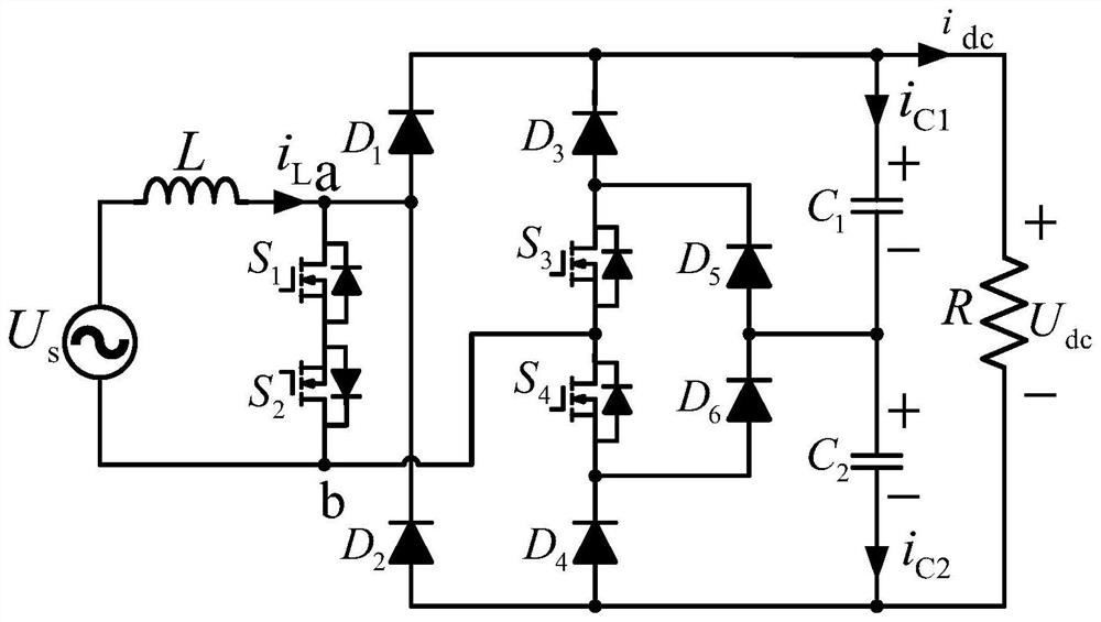
[0058] Such as figure 1 As shown, the diode clamped back-to-back bridgeless three-level rectifier includes: a back-to-back structure, a diode clamped voltage stabilizing structure, and a single-phase three-level structure.

[0059] The back-to-back structure includes two power switch tubes: S 1 , S 2 , a back-to-back bidirectional switch structure composed of two switch tubes.

[0060] The diode clamp voltage regulator structure consists of a diode group D 5 、D 6 For series capacitor C 1 、C 2 The midpoint voltage is clamped and regulated.

[0061] The structure of the diode-clamped back-to-back bridgeless three-level rectifier includes four diodes D 1 、D 2 、D 3 、D 4 , 2 power switching devices S 3 , S 4 , capacitance C 1 、C 2 . Diode D 1 The anode of the D 2 The cathode of the diode is connected to one end of the AC power supply and one end of the back-to-back bidirectional switch, and the diode D 3 The anode of the fully controlled switching tube S 3 The so...


PUM


Abstract

A diode-clamped back-to-back bridgeless three-level rectifier, comprising a power supply inductance series branch; a bidirectional transistor connected in parallel with the power supply inductance branch, a bidirectional transistor connected in series with the power supply inductance branch, and two sets of bidirectional transistors forming a PWM rectifier circuit; The midpoint voltage of the series capacitor is clamped by a diode bank. The three-level rectifier circuit is a three-level rectifier composed of 4 fully-controlled power switch tubes, 6 ordinary diodes, and 2 polarized capacitors. Compared with the traditional two-level rectification circuit, the voltage stress requirement on circuit components is reduced. When the rectifier circuit is in operation, no more than three semiconductor devices flow through it, and the circuit operation loss is small; only one switch tube needs to be changed to switch the circuit operation mode, thereby effectively reducing the circuit switching loss. The DC bus is operated by two capacitors in series, effectively reducing the output current ripple.

Description

technical field [0001] The invention relates to the technical field of single-phase three-level active rectifiers, in particular to a diode-clamped back-to-back bridgeless three-level rectifier. Background technique [0002] The power factor correction circuit can improve the power factor of the electrical equipment and reduce the reactive power generated by the equipment. The flow of reactive power in the grid will inevitably increase the loss of electric energy transmission in the grid, resulting in economic losses. In order to reduce the reactive power input to the grid by the load side and isolate the high-order harmonics in the grid that are harmful to the electrical equipment, more and more targeted power electronic devices are put into the electrical equipment. At the same time, adding power electronic devices to electrical equipment can effectively solve these harmful high-order harmonics. Diode-clamped back-to-back bridgeless three-level rectifier The bidirectiona...

Claims


Application Information

Patent Timeline
Patent Type & Authority Patents(China)
IPC IPC(8): H02M7/217H02M1/14
CPCH02M7/217H02M1/14
Inventor 马辉曾雨涵周沫函邹旭
Owner CHINA THREE GORGES UNIV
Why Eureka
Try Eureka