A production line for surface coating of mechanical metal parts

A technology for surface coating and metal parts, applied in the field of mechanical metal parts surface coating production line, can solve the problems of affecting the coating quality, uneven thickness of the coating surface, etc., to achieve improved quality, improved practicability, uniform and stable adhesion Effect

Active Publication Date: 2022-07-05
江苏光明环境设备有限公司
View PDF6 Cites 0 Cited by
  • Summary
  • Abstract
  • Description
  • Claims
  • Application Information

AI Technical Summary

Problems solved by technology

[0002] As we all know, the mechanical metal parts surface coating production line is an auxiliary device for mechanical metal parts surface coating, which has been widely used in the field of coating; the existing mechanical metal parts surface coating production line includes the first Slide rail, electrophoresis tank, first moving ring and first slider, the right part of the first slide rail is provided with a curved arc, the electrophoresis tank is installed under the curved arc, the first moving ring passes through two groups of first sliders and the first slider Rail sliding connection; when the existing mechanical metal parts surface coating production line is used, the metal parts to be coated are hung on the bottom of the first moving ring with iron wires, and the parts move from right to left into the electrophoresis tank and the coating is completed. It can be transferred to the left; in the use of the existing mechanical metal parts surface coating production line, it is found that after the parts leave the electrophoresis tank, the coating surface will be affected by gravity, which will cause uneven thickness of the coating surface, thus affecting the coating quality

Method used


Image

  • A production line for surface coating of mechanical metal parts
  • A production line for surface coating of mechanical metal parts
  • A production line for surface coating of mechanical metal parts

Examples


Embodiment Construction

[0018] The specific embodiments of the present invention will be described in further detail below with reference to the accompanying drawings and embodiments. The following examples are intended to illustrate the present invention, but not to limit the scope of the present invention.

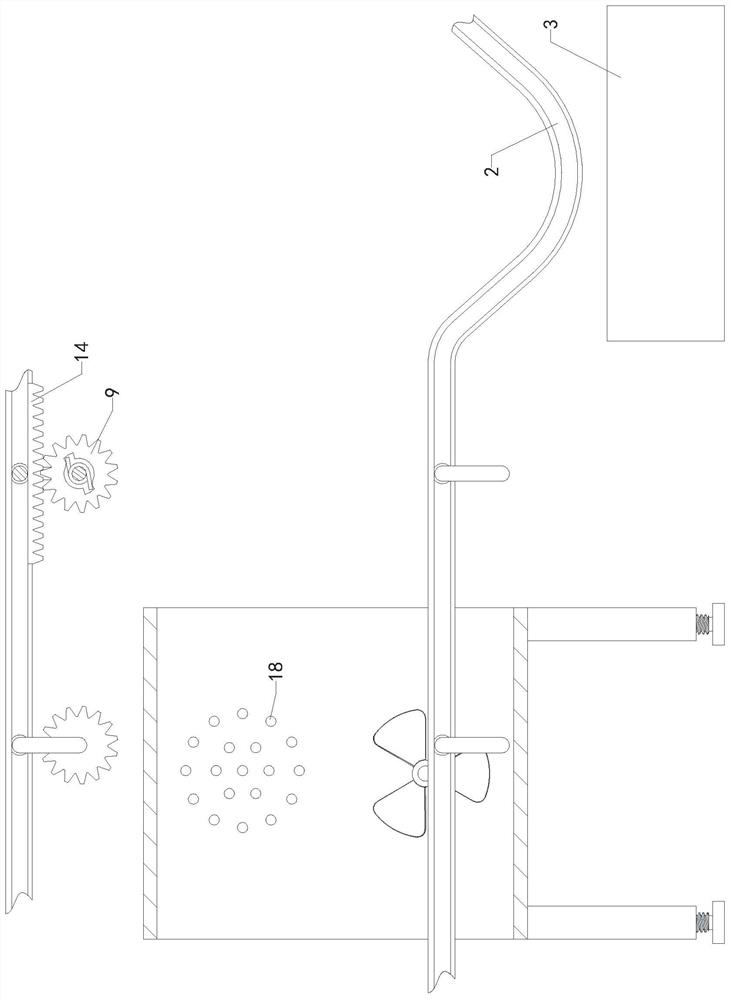
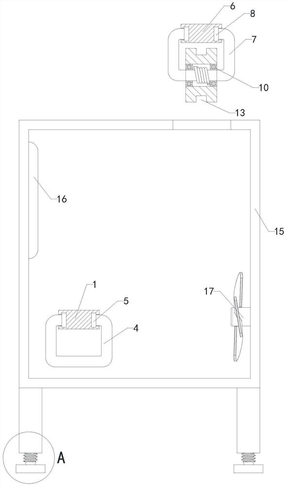
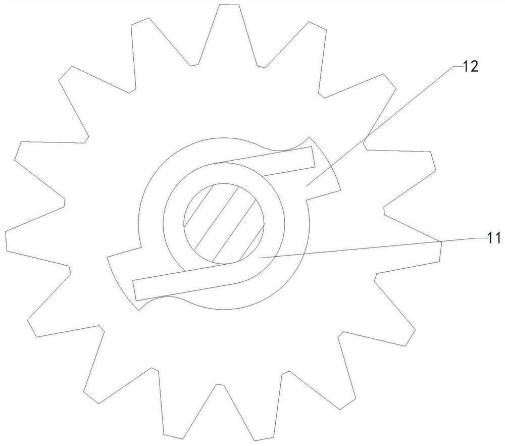
[0019] like Figure 1 to Figure 4 As shown, a surface coating production line for mechanical metal parts of the present invention includes a first sliding rail 1, an electrophoresis tank 3, a first moving ring 4 and a first sliding block 5, and the right part of the first sliding rail 1 is provided with a curved arc 2. The electrophoresis tank 3 is installed under the curved arc 2, and the first moving ring 4 is slidably connected to the first sliding rail 1 through two sets of first sliders 5; it also includes a second sliding rail 6, a second moving ring 7, a second Slider 8, gear 9, bearing 10, torsion spring 11 and heating tube 16, the second slide rail 6 is installed obliquely above the f...


PUM


Abstract

The invention relates to the technical field of painting, in particular to a surface painting production line for mechanical metal parts, which makes the paint evenly and stably adhere to the surface of the parts, improves the quality of painting and improves practicability; a groove, a first moving ring and a first sliding block, the right part of the first sliding rail is provided with a curved arc, the electrophoresis groove is installed under the curved arc, and the first moving ring is slidably connected to the first sliding rail through two sets of first sliding blocks; It also includes a second sliding rail, a second moving ring, a second sliding block, a gear, a bearing, a torsion spring and a heating tube, the second sliding rail is installed obliquely above the first sliding rail, and the second moving ring passes through two sets of second sliding The block is slidably connected with the second sliding rail, the gear is rotatably connected with the bottom of the second moving ring through two sets of bearings, the inner ring of the torsion spring is connected with the outer ring of the second moving ring, and two sets of clamping grooves are arranged in the middle of the gear.

Description

technical field [0001] The invention relates to the technical field of coating, in particular to a surface coating production line for mechanical metal parts. Background technique [0002] As we all know, the surface coating production line for mechanical metal parts is an auxiliary device for the surface coating of mechanical metal parts, which has been widely used in the field of painting; the existing surface coating production lines for mechanical metal parts include the first The slide rail, the electrophoresis tank, the first moving ring and the first slider, the right part of the first slide rail is provided with a curved arc, the electrophoresis tank is installed under the curved arc, and the first moving ring passes through the two sets of first sliders and the first slider. Rail sliding connection; when using the existing mechanical metal parts surface coating production line, hang the metal parts to be painted on the bottom end of the first moving ring with iron w...

Claims


Application Information

Patent Timeline
Patent Type & Authority Patents(China)
IPC IPC(8): F26B15/12F26B21/00F26B25/06C25D13/22
CPCF26B15/12F26B21/001F26B21/004F26B25/06C25D13/22Y02P70/10
Inventor 赵荣松赵荣海单志清
Owner 江苏光明环境设备有限公司
Why Eureka
Try Eureka