
Mortise and tenon joint structure for gate

A mortise-and-mortise and gate technology, which is used in the connection of rods, connecting components, mechanical equipment, etc., can solve the problems of weak connection strength and difficult installation, and achieve the effects of large force strength, increased joint area and wide application range.

Pending Publication Date: 2021-05-28
HEBEI JUYUAN HYDRAULIC MACHINERY CO LTD
View PDF0 Cites 0 Cited by
  • Summary
  • Abstract
  • Description
  • Claims
  • Application Information

AI Technical Summary

Problems solved by technology

[0003] The purpose of the present invention is to provide a mortise and tenon structure for gates, which has high connection strength and long service life, and solves the problems of weak connection strength and difficult installation

Method used


Image

  • Mortise and tenon joint structure for gate
  • Mortise and tenon joint structure for gate
  • Mortise and tenon joint structure for gate

Examples


Embodiment Construction

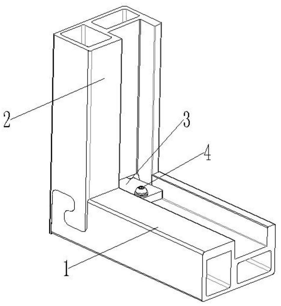
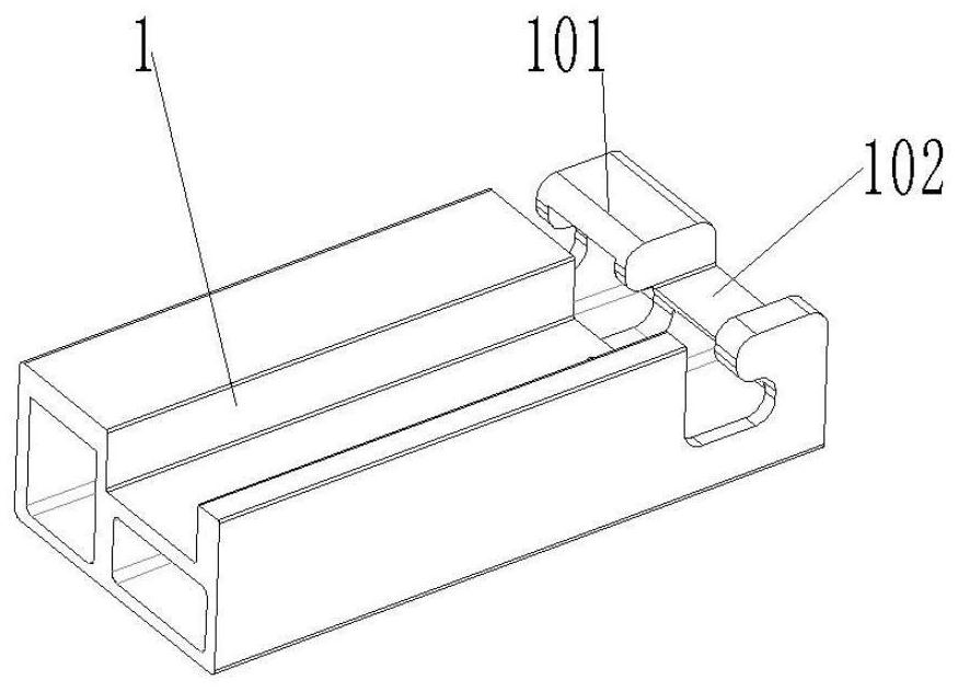
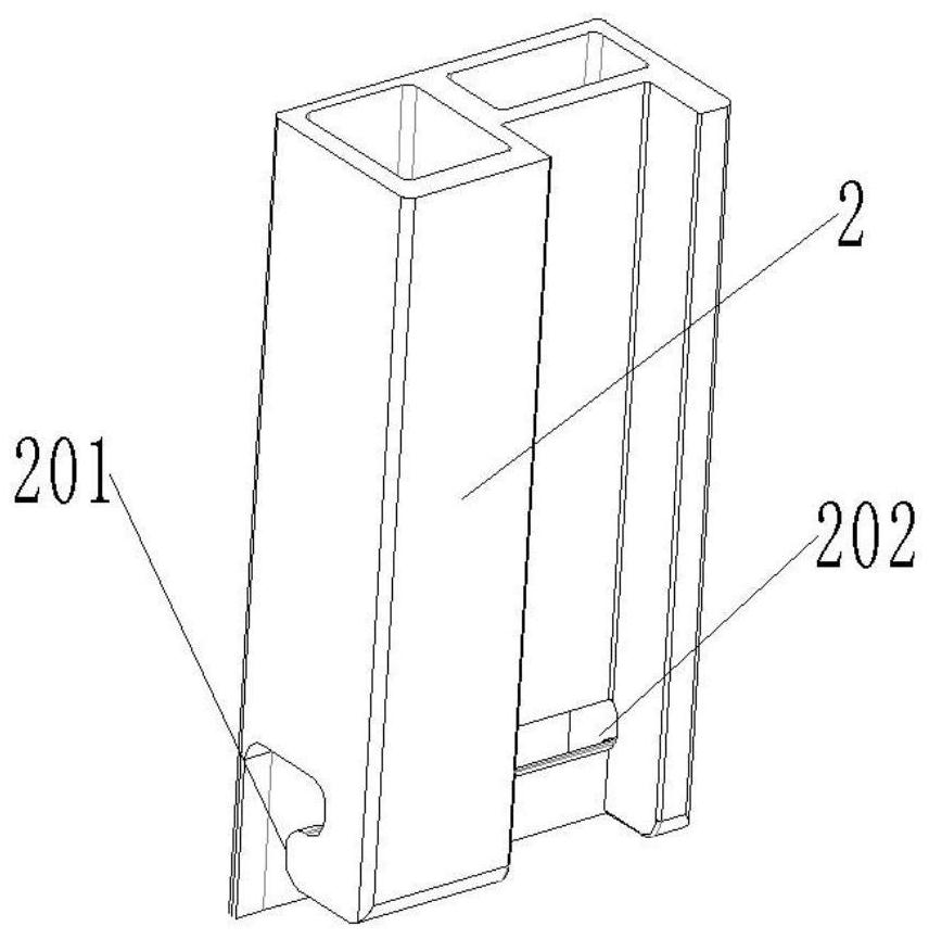
[0023] Such as figure 1 As shown, a mortise and tenon structure for a gate, including a horizontal profile 1, a vertical profile 2 and a stabilizer 3, the end of the horizontal profile 1 is provided with a first hook-shaped protrusion 101, and the end of the vertical profile 2 A second hook-shaped protrusion 201 is provided. The first hook-shaped protrusion 101 and the second hook-shaped protrusion hook 201 are connected together to form an insertion groove 102. After the stabilizer 3 is inserted into the insertion groove 102, it is fastened by a column The part 4 is fixed to realize the connection of the horizontal profile 1 and the vertical profile 2.

[0024] In this embodiment, the horizontal profile 1 and the vertical profile 2 are entangled with each other, and locked and fixed by the stabilizer 3 and the column fastener 4, thereby achieving a firm connection effect and convenient installation characteristics of the steel structure.

[0025] Specifically, refer to fig...


PUM


Abstract

The invention discloses a mortise and tenon joint structure for a gate. The mortise and tenon joint structure comprises a transverse sectional material, a vertical sectional material and a stabilizing piece, a first hook-shaped protrusion is arranged at the end of the transverse sectional material, a second hook-shaped protrusion is arranged at the end of the vertical sectional material, the first hook-shaped protrusion and the second hook-shaped protrusion are in butt joint to form an inserting groove, the stabilizing piece is fixed through a cylindrical fastener after being inserted into the inserting groove, and connection of the transverse sectional material and the vertical sectional material is achieved. The mortise and tenon joint structure is reasonable in structural design, simple and convenient in production and installation process, low in cost, wide in application range, firm in connection and high in stress strength, and large-scale industrial production can be realized.

Description

technical field [0001] The invention relates to the field of profile mortise and tenon wedge connection structures, in particular to a mortise and tenon structure for gates. Background technique [0002] There are two traditional corner connections between profiles, one is through welding, riveting and screw connection, the operation of this connection method is more complicated, the operator requires high skills, and many equipment and tools must be equipped for operation. The cost is high, and the popularization and application of the process is limited, especially welding. It is difficult to disassemble the profile after welding. It will cause damage to the structural frame formed by the profile. And after disassembly, the material will be deformed and cannot be reused, which is inconsistent with the concept of recycling in modern society; the second is to use components to connect two profiles together, such as special-shaped connecting plates, special-shaped connecting...

Claims


Application Information

Patent Timeline
IPC IPC(8): F16B7/00
CPCF16B7/00
Inventor 田永兴田永盛武洪占田恒建王朋
Owner HEBEI JUYUAN HYDRAULIC MACHINERY CO LTD
Learn More