Inner core bending mechanism for wheel speed sensor

A technology of wheel speed sensor and bending mechanism, applied in the field of bending mechanism, can solve the problems of high working intensity of workers, troublesome and inconvenient use, etc., achieve high bending processing efficiency, high unloading efficiency, and reduce weight, cost and power. consumption effect

Inactive Publication Date: 2021-05-28
赵瑞霞
View PDF1 Cites 0 Cited by
  • Summary
  • Abstract
  • Description
  • Claims
  • Application Information

AI Technical Summary

Problems solved by technology

[0005] The purpose of the present invention is to provide a bending mechanism for the inner core of the wheel speed sensor, so as to solve the above-mentioned background technology that needs to manually unload the bent inner core frequently, and the high-frequency repeated operation causes the worker's work intensity to be high , it is troublesome and inconvenient to use

Method used


Image

  • Inner core bending mechanism for wheel speed sensor
  • Inner core bending mechanism for wheel speed sensor
  • Inner core bending mechanism for wheel speed sensor

Examples


Embodiment Construction

[0028] The following will clearly and completely describe the technical solutions in the embodiments of the present invention with reference to the accompanying drawings in the embodiments of the present invention. Obviously, the described embodiments are only some of the embodiments of the present invention, not all of them.

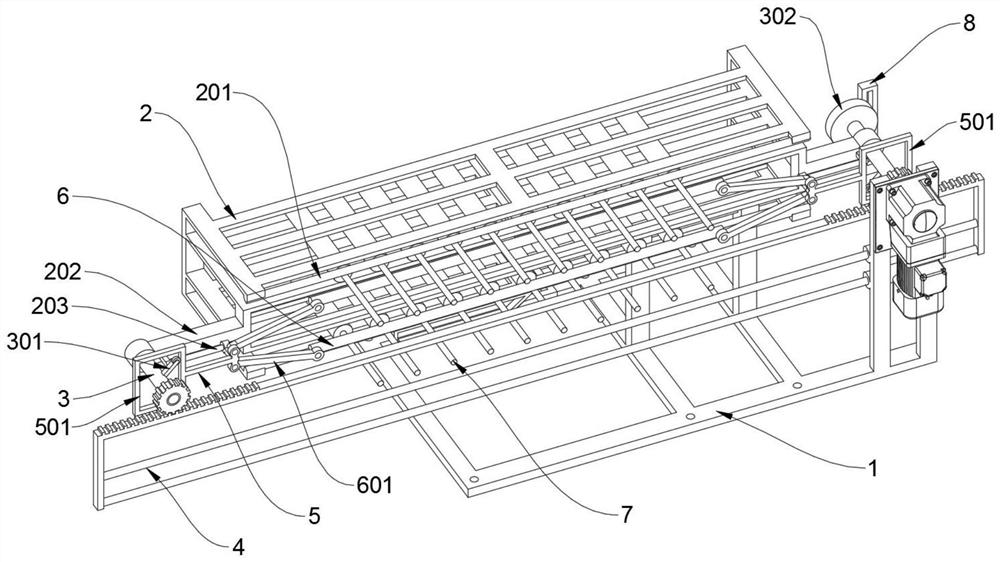
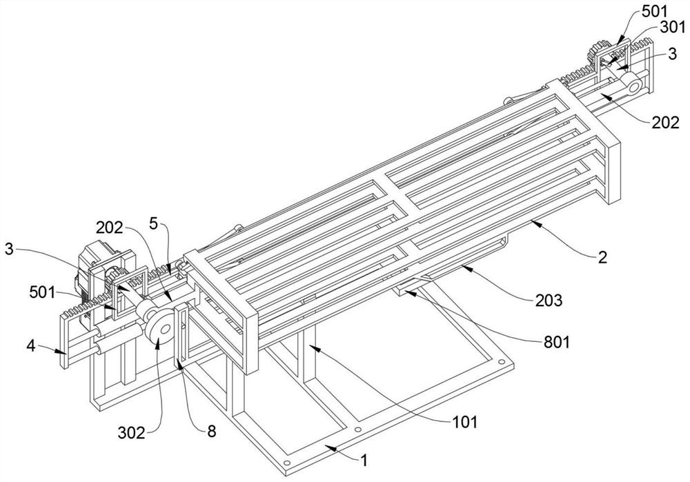
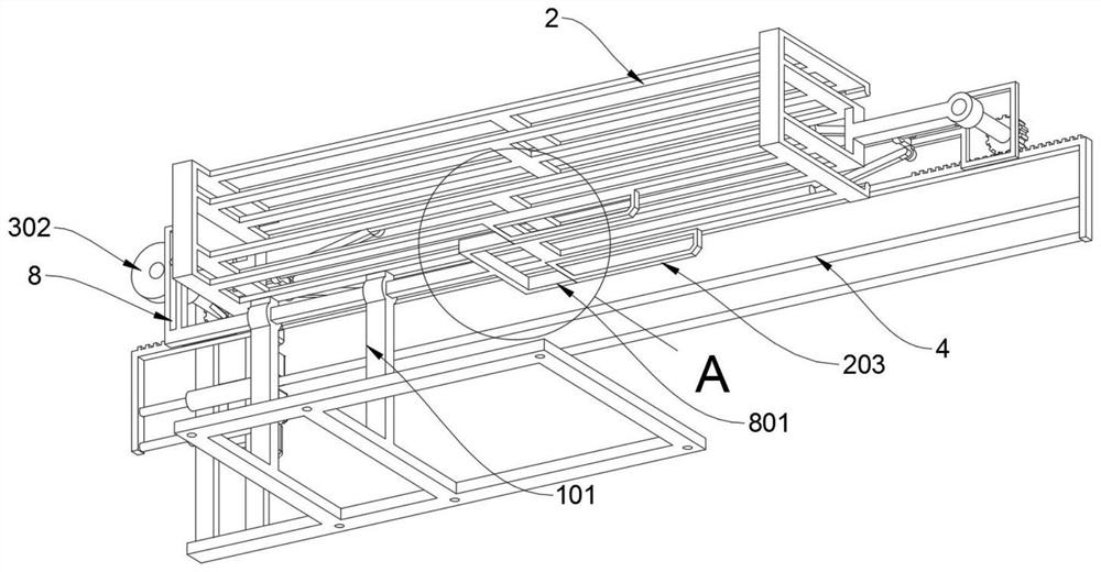
[0029] see Figure 1 to Figure 8 , an embodiment provided by the present invention: a wheel speed sensor inner core bending mechanism, including a base 1, the base 1 includes a vertical support rod 101, the base 1 has a rectangular structure as a whole, and two places are welded at intervals in the middle of the top end Vertical support rods 101, an L-shaped drive rod 8 is inserted through the top sections of the two vertical support rods 101, and the right end of the base 1 is locked and vertically supported. There is a motor on the shaft of the reducer of the motor A rotating shaft 3 is installed; a positioning frame 2 is installed on the right rotati...


PUM


Abstract

The invention discloses an inner core bending mechanism for a wheel speed sensor, relates to the technical field of bending mechanisms, and solves the problems that an existing inner core bending mechanism is required to manually and frequently unload bent inner cores, the relatively-high working intensity of workers is caused by high-frequency repeated operation, and the existing inner core bending mechanism is more troublesome, strenuous and inconvenient to use. The inner core bending mechanism for the wheel speed sensor comprises a base, the base comprises vertical supporting rods, the whole base is of a rectangular structure, the two vertical supporting rods are welded to the middle of the top end of the base at an interval, an L-shaped driving rod is inserted into the top end sections of the two vertical supporting rods in a penetrating mode, a motor is locked and vertically supported at the right end of the base, and a rotating shaft is mounted on a speed reducer of the motor in a coupling manner; and a positioning frame is rotationally mounted on the rotating shaft on the right side in a sleeving manner. The L-shaped driving rod is driven by a driving wheel and can share the same motor with two bending shafts, so that a driving motor additionally matched with the positioning frame is omitted, and the weight, the manufacturing cost and the power consumption of equipment are reduced.

Description

technical field [0001] The invention relates to the technical field of bending mechanisms, in particular to an inner core bending mechanism of a wheel speed sensor. Background technique [0002] The passive wheel speed sensor is a kind of wheel speed sensor, which is composed of a shell and a sensor core. The sensor core is equipped with a coil, pins and a skeleton. In order to facilitate packaging, the pins protrude from the packaged shell. In the subsequent process, the operator needs to bend the protruding pins. In the current market, there is no targeted bending device, and most of them are bent manually, which requires a lot of manpower and labor, and the efficiency is low. It is urgent to design a bending mechanism for the inner core of the wheel speed sensor to meet the production needs of batch processing. [0003] For example, the patent No. CN201820029486.5 discloses a wheel speed sensor inner core pin bending device, including: base plate, side support plate, hor...

Claims


Application Information

Patent Timeline
Patent Type & Authority Applications(China)
IPC IPC(8): B21F1/00
CPCB21F1/004
Inventor 赵瑞霞
Owner 赵瑞霞
Why Eureka
Try Eureka