
Hole detection and straightening equipment and detection and straightening method

A technology for testing equipment and equipment, which is applied in the field of mechanical processing and can solve problems such as principle errors

Pending Publication Date: 2021-05-28
ZHONGBEI UNIV
View PDF0 Cites 0 Cited by
  • Summary
  • Abstract
  • Description
  • Claims
  • Application Information

AI Technical Summary

Problems solved by technology

Various approximation methods are also used in the factory, for example, using an ultrasonic thickness gauge to estimate whether the deep hole is deflected by measuring the wall thickness of the deep hole. Of course, this method has a principle error

Method used


Image

  • Hole detection and straightening equipment and detection and straightening method
  • Hole detection and straightening equipment and detection and straightening method
  • Hole detection and straightening equipment and detection and straightening method

Examples


specific Embodiment approach

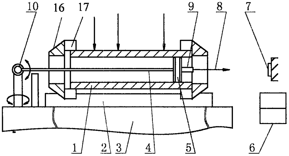
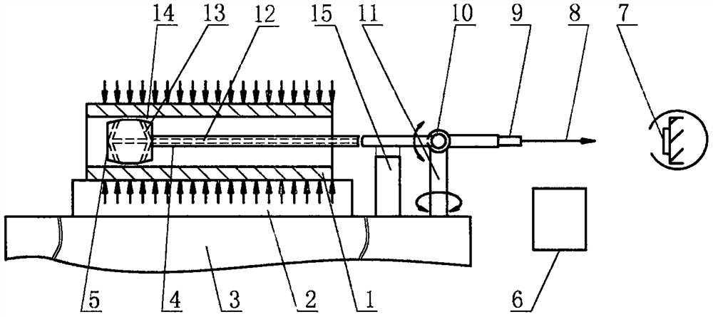
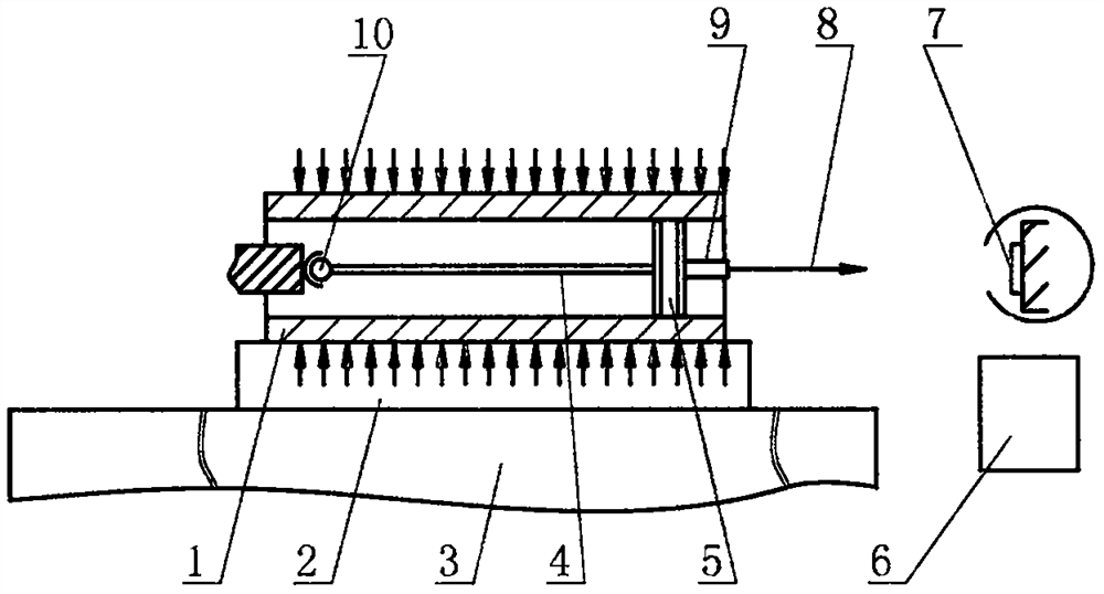
[0049] The specific implementation of the probe head: the probe head is in contact with the inner wall of the hole along a range of 360 degrees or within a range of less than 360 degrees; or, the probe head is not in direct contact with the hole wall, and there is a pressurized gas between the two.

[0050] Specific implementation of the detection rod: there is no hole or a hole in the detection rod.

Embodiment approach

[0051] Fulcrum implementation: The fulcrum is connected to a fixed object or connected to a rotatable object (eg, a support).

[0052] Detection part implementation mode: integral type or split type.

[0053] Afterburner mode: one-point afterburner, two-point afterburner, multi-point afterburner.

[0054] When using the moment of inertia method to evaluate the straightness of the hole, the Z-axis or X-axis or Y-axis of the coordinate system of the testing equipment is consistent with the direction of the hole axis.


PUM


Abstract

The invention belongs to the field of machining, and particularly relates to hole detection and correction equipment and a detection and correction method. Detection equipment, straightening equipment, a detection method and a straightening method are included. When the equipment moves relative to a reference part, a detection part moves around a fulcrum, and the straightness of a hole is obtained according to a light spot and change information thereof. The magnitude of the force of a special assistor is related to the error of the axis of the hole. The straightness of the hole is solved by adopting a minimum containing area method or a least square method or a two-end-point connecting line method or a rotational inertia method. The rotational inertia method comprises the steps of establishing a coordinate system OXYZ; assigning measuring points with mass and rigidization; solving rotational inertia, an inertia product, an inertia matrix, a diagonal matrix thereof and a main inertial coordinate system O'X'Y'Z' of a rigid body; and solving the straightness by projection. The straightening method comprises the steps of calculating the straightness of the hole; applying force for straightening; and repeating detection and force application. The optical amplification principle is adopted, errors caused by the rotation of the detection part around the axis thereof are reduced, friction is small, and the equipment and the method can be used for large-diameter holes and small-diameter holes.

Description

technical field [0001] The invention belongs to the field of mechanical processing, and in particular relates to hole detection and correction equipment and a detection and correction method. Background technique [0002] The relevant literature of the machinery industry introduces the algorithm of straightness error evaluation. Commonly used are the minimum contained area method, the two-end point connection method, and the least squares method. The evaluation of the straightness of the hole or deep hole axis is often based on the above method. Various approximation methods are also used in the factory, for example, using an ultrasonic thickness gauge to estimate whether the deep hole is deflected by measuring the wall thickness of the deep hole. Of course, this method has a principle error. [0003] Common straighteners are used to straighten the straightness of wires such as straightened steel wires. Some enterprises produce equipment for straightening pipes. The strai...

Claims


Application Information

Patent Timeline
IPC IPC(8): B21C51/00B21D3/00G01B11/00
CPCB21C51/00B21D3/00G01B11/00
Inventor 于大国赵明王峰赵晓巍
Owner ZHONGBEI UNIV
Learn More