
Electromagnetic ammunition capable of being launched by conventional gunpowder launcher

An ammunition and electromagnetic technology, which is applied to weapons, ammunition, projectiles and other directions without explosives, can solve the problems of insufficient export speed of gunpowder launching technology, incompatibility of artillery and ammunition with electromagnetic propulsion, etc., to improve anti-armor capability and enhance strike capability. , good concealment effect

Active Publication Date: 2021-05-25
INST OF ELECTRICAL ENG CHINESE ACAD OF SCI
View PDF8 Cites 0 Cited by
  • Summary
  • Abstract
  • Description
  • Claims
  • Application Information

AI Technical Summary

Problems solved by technology

[0003] The technical problem to be solved by the present invention is: to overcome the deficiency of the exit speed of the existing gunpowder launch technology and the defect that the electromagnetic propulsion cannot be compatible with the traditional artillery ammunition, and to provide an electric ammunition device and method that can be used on the traditional artillery launcher, The shape and structure of this kind of electric ammunition can be consistent with that of traditional artillery shells, and the loading and use methods are also the same, except that the shells are not filled with traditional gunpowder.

Method used


Image

  • Electromagnetic ammunition capable of being launched by conventional gunpowder launcher
  • Electromagnetic ammunition capable of being launched by conventional gunpowder launcher
  • Electromagnetic ammunition capable of being launched by conventional gunpowder launcher

Examples


Embodiment Construction

[0018] The present invention will be further described below in conjunction with the accompanying drawings and specific embodiments.

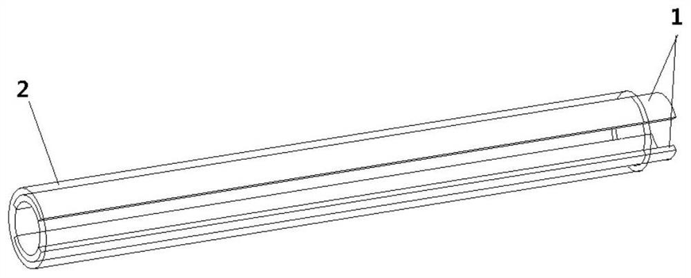
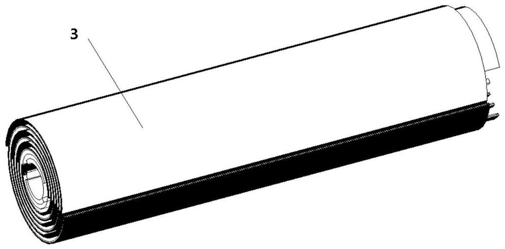
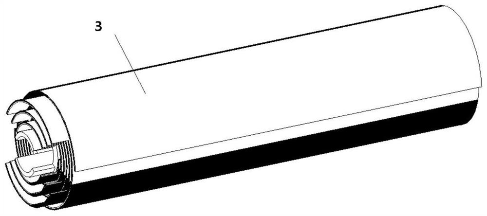
[0019] The invention proposes an electric ammunition that can be used in traditional gunpowder launchers, which utilizes the advantage of electromagnetic propulsion to break through the limit speed of gunpowder launch, and is compatible with traditional artillery launch. Two parallel tile-shaped metal strips, the metal can be made of copper alloy, etc., symmetrically inlaid on the inner wall of the insulating sleeve, the insulating sleeve can be made of insulating materials such as epoxy glass fiber reinforced plastics, the outlet of the tile-shaped metal strip and the insulating sleeve The barrel is flat, a part of the tail protrudes, and a cylindrical cavity is formed inside, which can be called a firing cavity. The insulating sleeve is tightly wound with a composite film made of two layers of conductive foil and insulating foil material. The...


PUM


Abstract

The invention relates to an electromagnetic ammunition capable of being launched by a conventional gunpowder launcher, which is characterized in that two parallel tile-shaped metal strips are symmetrically inlaid on the inner wall of an insulating sleeve, and two layers of composite films made of conductive foils and insulating foil materials tightly wind outside the insulating sleeve in a lapping manner, the two composite films and the two tile-shaped metal strips are connected through two fan-shaped metal blocks respectively, and each fan-shaped metal block is provided with an electrode protruding backwards. A metal primer, bullets and a detachable holding seat are tightly pressed in a launching cavity, the metal primer is located on the outer side of the bottom of a cartridge case, the device is wrapped by the cartridge case, an insulating lining is arranged in the cartridge case and insulates the cartridge case from all internal parts, and the front end of the insulating lining is open. Before battle preparation, positive and negative electrodes of a vehicle-mounted high-voltage charger make contact with two electrodes at the tail of the electric ammunition for several seconds, the electric ammunition is disconnected after voltage balance is achieved, the electric ammunition is loaded into an artillery bore, like a traditional artillery, a firing pin is used for firing the metal primer, electric energy stored in the ammunition is instantly released, and the bullets and the detachable holding seat are pushed out at a high speed.

Description

technical field [0001] The invention relates to the technical field of electromagnetic propulsion, in particular to an electromagnetic ammunition that can be launched by a conventional gunpowder launcher. Background technique [0002] Existing traditional gunpowder launchers and ammunition have mature technology, wide popularity, and strong adaptability, but because the gas expansion speed after the gunpowder is ignited has an upper limit (about 2km / s, that is, the exit speed of the projectile launched by the traditional artillery cannot exceed this value), with the development of armor protection technology and other combat units and combat concepts, traditional gunpowder launchers are becoming more and more insufficient. Electromagnetic propulsion uses electromagnetic force to launch loads or projectiles, and the exit speed can break through the upper limit of the speed of traditional propellant propulsion devices. It is one of the alternative technology options for tradit...

Claims


Application Information

Patent Timeline
Patent Type & Authority Applications(China)
IPC IPC(8): F41B6/00F42B30/00
CPCF41B6/00F42B30/00
Inventor 王厚生关永超王建超马本栋李然彭爱武
Owner INST OF ELECTRICAL ENG CHINESE ACAD OF SCI
Learn More