
Asphalt mixing device

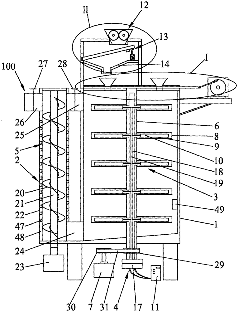
A mixing device and asphalt technology, applied in mixers, mixing methods, fluid mixers, etc., can solve problems affecting the quality of finished products, difficulty in mixing asphalt and ingredients evenly, and affecting the fluidity of asphalt

Pending Publication Date: 2021-05-25
河北中科同创科技发展有限公司
View PDF7 Cites 6 Cited by
  • Summary
  • Abstract
  • Description
  • Claims
  • Application Information

AI Technical Summary

Problems solved by technology

[0003] In the actual production process, the asphalt is generally added to the mixing tank to preheat, and then the ingredients to be added are added to the mixing tank, heated and mixed, so that the asphalt and the ingredients are mixed evenly. However, the existing mixing tank has a large volume , while the heating device can only heat the surface of the mixing tank, and it is difficult to heat the middle area of ​​the mixing tank in place. If the asphalt temperature in the middle is too low, it will cause sticking, so that the stirring cannot be continued, which affects the production process, making it difficult to mix the asphalt and ingredients evenly. , affecting the quality of finished products; in actual production, due to the phenomenon of large particles in the ingredients, directly adding to asphalt for stirring will affect the quality of the final product. When adding asphalt, due to the low temperature of the ingredients, it will Reduce the local temperature of asphalt, thereby affecting the fluidity of asphalt, which may also lead to the occurrence of adhesion; moreover, the traditional mixing device is usually a single-shaft mixer, which only makes a single horizontal circular motion, and cannot mix the asphalt and ingredients evenly. The physical or chemical reaction between the two cannot fully occur, which affects the quality of the finished product

Method used


Image

  • Asphalt mixing device
  • Asphalt mixing device
  • Asphalt mixing device

Examples


Embodiment Construction

[0023] The following will clearly and completely describe the technical solutions in the embodiments of the present invention with reference to the accompanying drawings in the embodiments of the present invention. Obviously, the described embodiments are only some, not all, embodiments of the present invention. Based on the embodiments of the present invention, all other embodiments obtained by persons of ordinary skill in the art without making creative efforts belong to the protection scope of the present invention.

[0024] The purpose of the present invention is to provide an asphalt mixing device to solve the problems existing in the prior art. The heating effect is good, the mixing is more uniform, and the quality of the finished product is guaranteed.

[0025] In order to make the above objects, features and advantages of the present invention more comprehensible, the present invention will be further described in detail below in conjunction with the accompanying drawin...


PUM


Abstract

The invention discloses an asphalt mixing device, and relates to the technical field of asphalt production and processing. A vertical lifting device is fixedly connected with a mixing box, the vertical lifting device can lift asphalt on the bottom layer in the mixing box to the surface layer, and a second heating device can heat the asphalt in the vertical lifting device. A stirring shaft is rotatably connected into the mixing box around a vertical shaft, a plurality of stirring rods are fixedly arranged on the circumferential face of the stirring shaft, a heating cavity is formed in each stirring rod, and a heating rod is fixedly installed in each heating cavity. A smashing device is fixedly arranged at the top of the mixing box, and a vibration screening device is arranged below the smashing device. A collecting disc is arranged below the vibration screening device and can collect screened ingredients, a first hopper is arranged below a discharging port of the collecting disc, the first hopper is fixedly arranged at the top of the mixing box and is communicated with the mixing box, and a third heating device is fixedly arranged on the outer surface of the first hopper. The heating effect is good, mixing is more uniform, and the finished product quality is guaranteed.

Description

technical field [0001] The invention relates to the technical field of asphalt production and processing, in particular to an asphalt mixing device. Background technique [0002] Bitumen is a dark brown complex mixture composed of hydrocarbons of different molecular weights and their non-metallic derivatives. It is a kind of high-viscosity organic liquid, and it mostly exists in the form of liquid or semi-solid petroleum. When bitumen is used, such as in When adding coarse aggregate, fine aggregate, mineral powder and other substances to asphalt to prepare asphalt mixture, it needs to be carried out at a certain temperature to make the asphalt have a certain fluidity, so that the asphalt can be mixed with other substances to meet the production and processing requirements . [0003] In the actual production process, the asphalt is generally added to the mixing tank to preheat, and then the ingredients to be added are added to the mixing tank, heated and mixed, so that the a...

Claims


Application Information

Patent Timeline
IPC IPC(8): B01F13/10B01F3/20B01F7/18B01F7/24B01F5/10B01F15/02B01F15/00B01F15/06B01F23/70
CPCB01F23/70B01F23/713B01F25/52B01F27/191B01F27/213B01F27/92B01F27/90B01F33/831B01F35/2115B01F35/7163B01F2035/99B01F35/92B01F35/95B01F2101/38
Inventor 贾志军郭强贺佩齐光明
Owner 河北中科同创科技发展有限公司
Learn More