
EL defect unmanned aerial vehicle inspection method for on-site evaluation of energy equipment

A technology for unmanned aerial vehicles and equipment, which is applied in the field of inspection methods and systems for EL defect unmanned aerial vehicles, and can solve problems such as inapplicability to high-altitude photovoltaic arrays, low detection efficiency, and poor interface contact.

Inactive Publication Date: 2021-05-18
上海道口智能科技有限公司 +1
View PDF7 Cites 0 Cited by
  • Summary
  • Abstract
  • Description
  • Claims
  • Application Information

AI Technical Summary

Problems solved by technology

[0006] (1) Limited application scenarios: tripods are used as the carrier of the imaging system, and the height is limited, so it is not suitable for high-altitude photovoltaic arrays, such as water photovoltaic power stations, mountain photovoltaic power stations and rooftop photovoltaic power stations with installation heights greater than 3 meters;
[0007] (2) Low test efficiency: only one photovoltaic module can be tested at a time, the detection efficiency is low, and it is impossible to realize the on-site full inspection of photovoltaic modules;
[0008] (3) Electrical components are easily damaged: frequent plugging and unplugging of the power interface of the photovoltaic module during testing may easily cause poor contact of the interface, causing abnormal heating and fire;
[0009] (4) The evaluation efficiency of test results is low: one picture for each sample requires a lot of manual analysis

Method used


Image

  • EL defect unmanned aerial vehicle inspection method for on-site evaluation of energy equipment
  • EL defect unmanned aerial vehicle inspection method for on-site evaluation of energy equipment
  • EL defect unmanned aerial vehicle inspection method for on-site evaluation of energy equipment

Examples


Embodiment Construction

[0046] The present invention will be further described below in conjunction with the accompanying drawings. It should be noted that the following embodiments are based on the technical solution and provide detailed implementation and specific operation process, but the protection scope of the present invention is not limited to this embodiment .

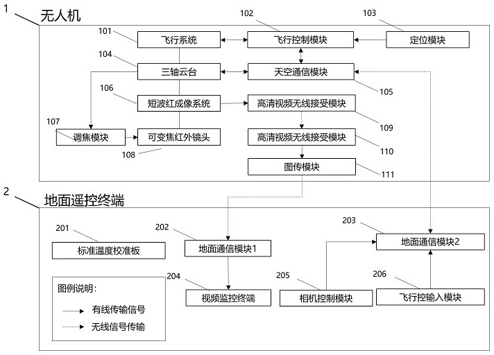
[0047] see figure 1 As shown, the structure of an EL defect UAV inspection system for on-site evaluation of energy equipment, which includes: UAV, flight system, flight control module, positioning module, three-axis gimbal, sky communication module, short-wave infrared Imaging system, image transmission module, high-definition video wireless transmitting module, high-definition video wireless receiving module, variable focus infrared lens, focusing module, temperature calibration board, ground remote control terminal, ground communication module 1, ground communication module 2, video monitoring terminal, Infrared camera focus contr...


PUM


Abstract

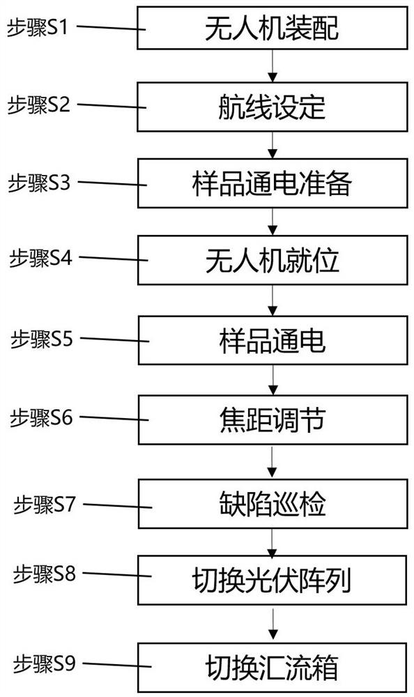
The invention provides an EL defect unmanned aerial vehicle inspection method and system for on-site evaluation of energy equipment. The method comprises the steps of route setting, unmanned aerial vehicle assembling, sample electrifying, focal length adjusting, EL defect inspection and the like. The invention further provides an EL defect unmanned aerial vehicle inspection system for energy equipment field evaluation. The EL defect unmanned aerial vehicle inspection system integrates a multi-rotor unmanned aerial vehicle system, a high-sensitivity short-wave infrared system, a remote infrared lens focusing module and a high-definition infrared image wireless real-time transmission module. Compared with a conventional handheld EL testing system, the EL testing system is wide in application scene, high in testing efficiency and capable of monitoring the defect inspection condition on line in real time and avoiding damage to a sample wiring terminal. According to the method, the safety, the quality and the benefit evaluation efficiency of green assets formed by taking photovoltaic power stations as groups is improved, and the safety and quality of on-site construction and operation links in the whole life cycle of key equipment of the green assets are effectively guaranteed.

Description

technical field [0001] The invention belongs to the field of on-site evaluation of energy equipment, and relates to an EL defect UAV inspection method and system. Background technique [0002] New energy photovoltaic power plants are asset-intensive green assets, and their core power generation components - photovoltaic modules account for more than 50% of the total value of assets. The safety and quality status of photovoltaic modules during on-site construction and operation are indicators that power plant owners, constructors, operators, investors and purchasers all focus on. [0003] Photovoltaic modules are key energy equipment for new energy photovoltaic power plants, and their entire life cycle includes production, transportation, installation and operation. In the production process, the photovoltaic module smart factory adopts efficient and intelligent online detection technology, which effectively guarantees the safety and quality of photovoltaic modules. However...

Claims


Application Information

Patent Timeline
IPC IPC(8): H04N7/18H04N5/232H04N5/33H04N5/907G05D1/08G05D1/10
CPCH04N7/18H04N5/33H04N5/907G05D1/0808G05D1/101H04N23/66H04N23/67
Inventor 彭云峰丁叶飞黄川
Owner 上海道口智能科技有限公司
Learn More