Self-consistent driving sensor, functional device and electric excitation method for realizing driving sensing

An electrical excitation and sensor technology, applied in piezoelectric/electrostrictive or magnetostrictive motors, electrical components, generators/motors, etc., to solve the problems of heavy mass, complex structure, and low precision of movement control

Inactive Publication Date: 2021-05-18
杨斌堂
View PDF1 Cites 0 Cited by
  • Summary
  • Abstract
  • Description
  • Claims
  • Application Information

AI Technical Summary

Problems solved by technology

The existing sensor-driven displacement device is mainly controlled by a motor. This structure leads to a complex product structure, heavy weight, and low movement control accuracy, which cannot meet the needs of modern industries for precise control and positioning.
[0003] Patent document CN107914199A discloses a pressure sensor shell grinding device, including a top plate, a suspension beam, a longitudinal slide rail, a lifting slide seat, a locking key, a rotating shaft, a first beam, a transverse slide rail, a first sliding sleeve, and a traverse cylinder , rocker arm, limit key pin, mounting arm, driving motor, cutting disc, grinding wheel, worktable, mounting frame, movable clamping joint, rotating motor, extrusion cylinder, workpiece, second beam and second sliding sleeve, However, this design uses separate devices for sensing and driving, resulting in complex structure and low precision of driving and sensing

Method used


Image

  • Self-consistent driving sensor, functional device and electric excitation method for realizing driving sensing
  • Self-consistent driving sensor, functional device and electric excitation method for realizing driving sensing
  • Self-consistent driving sensor, functional device and electric excitation method for realizing driving sensing

Examples


Embodiment 1

[0060]The present invention provides a self-consistent driving sensor, which includes a supporting shell 1, an electric excitation assembly, a driving body and a sensor, the electric excitation assembly and the driving body are installed on the supporting shell 1 and the electric excitation assembly Arranged along the circumferential direction of the driving body or connected to the end of the driving body, when the electric excitation component applies the first electric excitation, it can drive the driving body to produce a first deformation, thereby causing the sensor to produce a first The sensing signal, the first sensing signal is used to calibrate the reference value of the target detection quantity. When the electric excitation component applies a second electric excitation, it can drive the driving body to produce a second deformation, thereby causing the sensor to generate a second induction signal, and the second induction signal is used to obtain the measurement val...

Embodiment 2

[0077] This embodiment is a preferred example of Embodiment 1.

[0078] In this embodiment, a self-consistent driving sensor is provided, which can realize the driving function and realize the sensing function while realizing the driving, wherein the target detection quantity is displacement, such as figure 1 As shown, the electric excitation assembly includes a first coil 3 and a second coil 4, the sensor uses a first piezoelectric body 5, the driver uses a magnetostrictive body 2, and the first piezoelectric body 5 is connected to The magnetostrictive body 2 is arranged at the end of the magnetostrictive body 2, wherein, firstly, a first electric excitation V is applied to the second coil 4 a2 Afterwards, the first magnetic field is generated, wherein the first electric excitation adopts a high-frequency AC weak current, for example, the frequency is 10000 Hz, and the first magnetic field is a weak magnetic field, so that the magnetostrictive body 2 can produce a slight firs...

Embodiment 3

[0081] This embodiment is another preferred example of Embodiment 1.

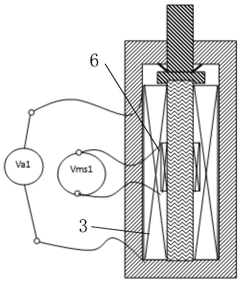
[0082] In this embodiment, a self-consistent driving sensor is provided, which can realize the driving function and realize the sensing function while realizing the driving, wherein the target detection quantity is displacement, such as figure 2 As shown, the electric excitation assembly includes a first coil 3, the sensor uses a third coil 6, the driver uses a magnetostrictive body 2, and the first coil 3 applies V a1 Electric excitation, specifically, the first electric excitation and the second electric excitation linearly superimposed on the frequency domain to generate the first magnetic field and the second magnetic field respectively, wherein the first electric excitation adopts high-frequency AC weak current, and the frequency is high frequency, for example 50000HZ, the first magnetic field is a weak magnetic field, and then the magnetostrictive body 2 can be made to produce a small first deformati...


PUM


Abstract

The invention provides a self-consistent driving sensor, a functional device and an electric excitation method for realizing driving sensing. The self-consistent driving sensor comprises a supporting shell, an electric excitation assembly, a driving body and a sensor, the electric excitation assembly and a magnetostriction body are both installed on the supporting shell, and the electric excitation assembly is arranged in the circumferential direction of the magnetostriction body or is connected with the end of the driving body. When the electric excitation assembly applies first electric excitation, the driving body can be driven to generate first deformation, so that the sensor can generate a first induction signal. When the electric excitation assembly applies second electric excitation, the driving body can be driven to generate second deformation, so that the sensor can generate a second induction signal. The first induction signal is used for calibrating a reference value of the target detection quantity, the second induction signal is used for obtaining the measurement value of the target detection quantity, and then the variable quantity of the target detection quantity can be obtained. According to the present invention, the driving sensor can sense during driving, and is simple in structure and high in measurement precision.

Description

technical field [0001] The invention relates to the technical field of drive sensors, in particular to a self-consistent drive sensor, functional equipment and an electrical excitation method for realizing drive sensing. Background technique [0002] The sensor-driven displacement device is mainly used in machining positioning and measuring devices, and controls the measurement and positioning through the corresponding relationship between the driving displacement and the sensing information. The existing sensor-driven displacement device is mainly controlled by a motor. This structure leads to complex structure, heavy weight, and low precision of movement control, which cannot meet the needs of modern industry for precise control and positioning. [0003] Patent document CN107914199A discloses a pressure sensor shell grinding device, including a top plate, a suspension beam, a longitudinal slide rail, a lifting slide seat, a locking key, a rotating shaft, a first beam, a tr...

Claims


Application Information

Patent Timeline
Patent Type & Authority Applications(China)
IPC IPC(8): H02N2/04H02N2/06
CPCH02N2/04H02N2/062
Inventor 杨斌堂
Owner 杨斌堂
Why Eureka
Try Eureka