Eureka AIR delivers breakthrough ideas for toughest innovation challenges, trusted by R&D personnel around the world.

Interconnected bare core interface management system and initialization method thereof

An initialization method and interface management technology, applied in the field of bare core interface management, can solve the problems of unfavorable system rapid construction, difficult design, and time-consuming reconstruction, so as to enhance configuration flexibility, overcome design difficulty, and improve construction speed effect

Active Publication Date: 2022-08-02
58TH RES INST OF CETC
View PDF3 Cites 0 Cited by
  • Summary
  • Abstract
  • Description
  • Claims
  • Application Information

AI Technical Summary

Problems solved by technology

However, the design of the state machine belongs to the category of hardware design. Its design is difficult, the process is complicated, and the reconstruction takes a long time, which is not conducive to the rapid construction of the system.

Method used


Image

  • Interconnected bare core interface management system and initialization method thereof
  • Interconnected bare core interface management system and initialization method thereof
  • Interconnected bare core interface management system and initialization method thereof

Examples


Embodiment 1

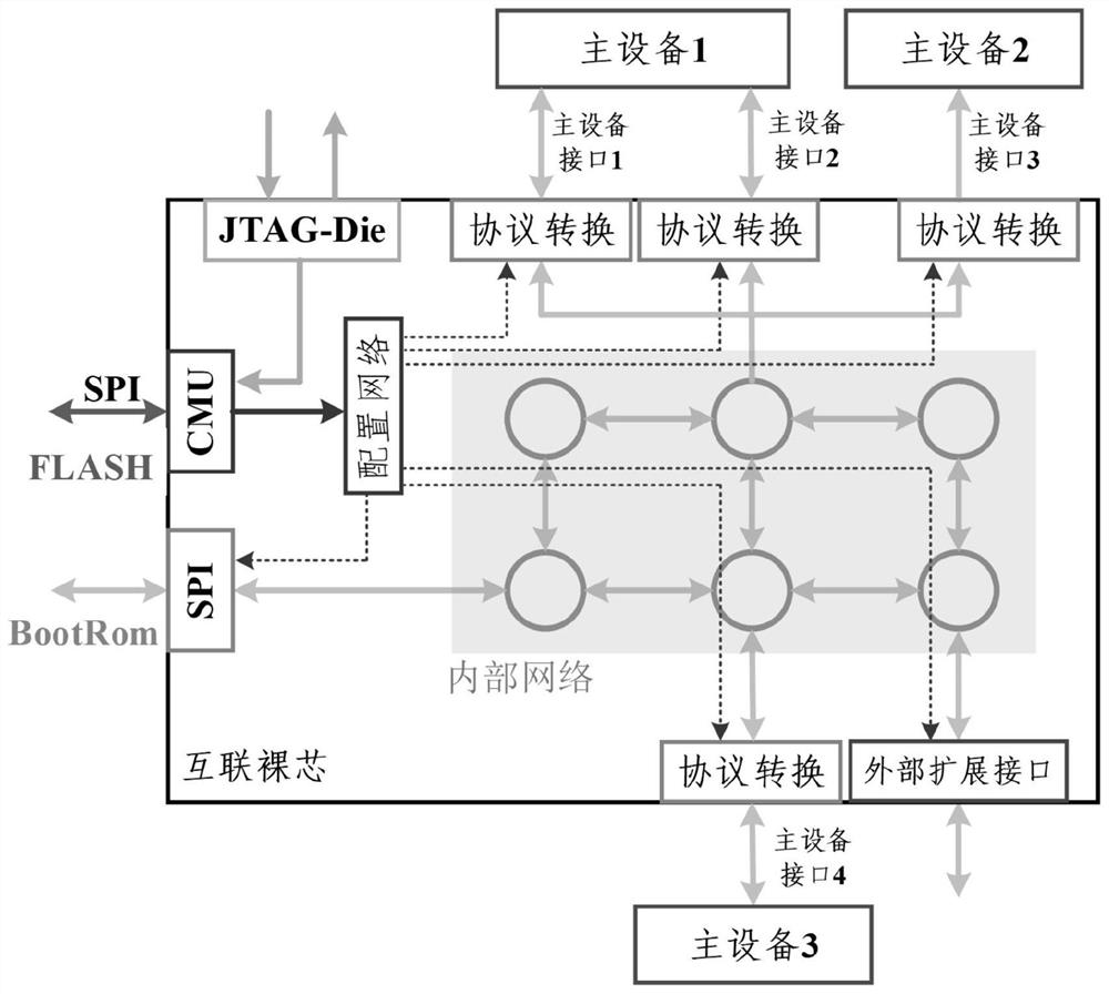
[0038] like figure 1As shown, the interconnected die interface management system includes: a CMU system, a JTAG-Die interface and a configuration network all connected to the CMU system; the CMU system includes a CMU processor and a Flash connected to the CMU processor, the Flash is used to store the software code of the CMU system; the JTAG-Die interface is used to control the startup of the CMU program; one end of the configuration network is connected to the CMU processor in the form of peripherals, and the other end is connected to each interface to be configured through an independent bus ; The CMU processor is used to transmit the configuration data to the function register of each interface to be configured through the configuration network and the independent bus when executing its configuration program, so as to realize the configuration of the interface address translation table.

[0039] The interconnect die interface management system is independent of all other bu...

Embodiment 2

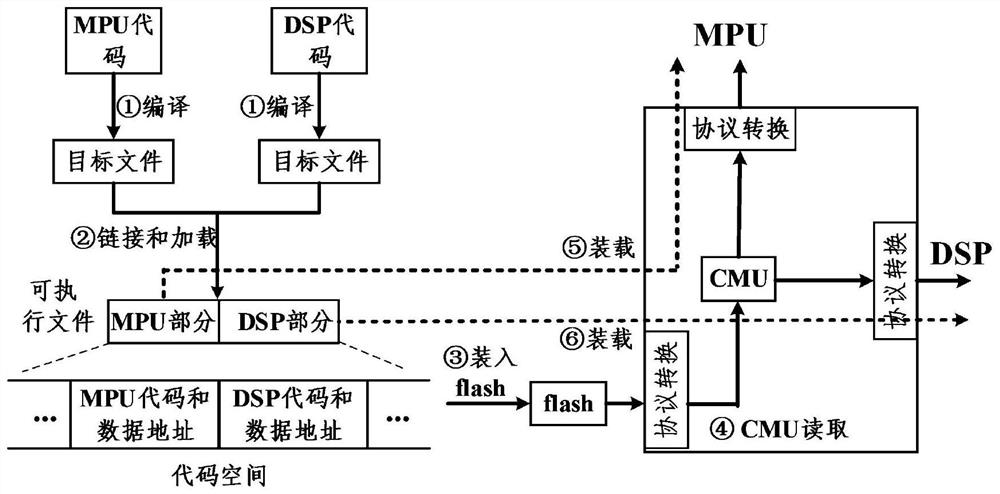
[0045] like figure 2 As shown, the initialization method of the interconnection die interface management system includes the following steps:

[0046] S101, compile the program codes of each master device respectively, and generate the target file;

[0047] S102, link the target file with the startup code provided by the system through the linker, generate an executable file, load the executable file into the specified code space, respectively correspond to the code address space of each master device, and be managed uniformly by the CMU system;

[0048] S103, the codes and data addresses of each master device in the code space are loaded into the program memory Flash of the CMU system respectively;

[0049] S104, start the CMU system through the JTAG-Die interface, load and execute the program in the Flash, generate control signals for each protocol conversion interface, and configure it;

[0050] S105, each master device sequentially reads and executes the startup code th...


PUM


Abstract

The invention relates to a bare core interface management, in particular to an interconnect bare core interface management system and an initialization method thereof. Interconnected die interface management system, including: CMU system, JTAG-Die interface and configuration network connected to CMU system; CMU system includes CMU processor and Flash connected to CMU processor, Flash is used to store software code of CMU system ; The JTAG‑Die interface is used to control the startup of the CMU program; one end of the configuration network is connected to the CMU processor in the form of peripherals, and the other end is connected to each interface to be configured through an independent bus; the CMU processor is used to execute its configuration program. It is transmitted to the function register of each interface to be configured through the configuration network and independent bus, so as to realize the configuration of the interface address translation table. The system uses the processor to realize the system initialization configuration, and converts the hardware configuration of the interface into software programming, which reduces the design difficulty, simplifies the development process, enhances the configuration flexibility, and helps to improve the system construction speed.

Description

technical field [0001] The invention relates to a bare core interface management, in particular to an interconnect bare core interface management system and an initialization method thereof. Background technique [0002] With the development of digital integrated circuits, system-on-chip (Systemon Chip, SoC, refers to the integration of multiple functional modules on the same silicon chip) has almost become a necessary solution to achieve high-performance systems, manufacturers continue to expand the scale of SoC by To meet the user's demand for product performance. However, limited by factors such as processing technology, Moore's Law (that is, the law that the number of transistors that can be accommodated on an integrated circuit doubles every 24 months) is gradually failing, which makes it difficult to expand the scale of integrated circuits on a single silicon wafer. Costs and development cycles become extremely high. [0003] The interconnected die is a general stand...

Claims


Application Information

Patent Timeline
Patent Type & Authority Patents(China)
IPC IPC(8): G06F13/42G06F15/78G06F9/445G06F8/36
CPCG06F13/4282G06F15/7807G06F9/44521G06F9/44505G06F8/36
Inventor 魏敬和黄乐天于宗光曹文旭孙晓冬刘国柱
Owner 58TH RES INST OF CETC
Why Eureka
Eureka Blog
Learn More