Engineering monitoring test monitoring equipment
A monitoring equipment and engineering monitoring technology, which is applied in the directions of measuring devices, measuring instruments, surveying and mapping, and navigation, etc., can solve the problems of unprotected level gauges, the use of level gauges that cannot be mobilized at height, and inconvenient to use.
- Summary
- Abstract
- Description
- Claims
- Application Information
AI Technical Summary
Problems solved by technology
Method used
Image
Examples
Embodiment 1
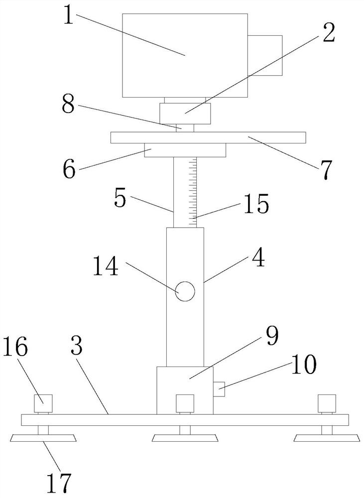
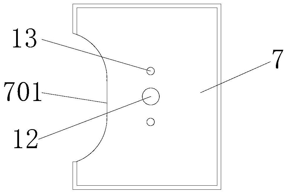
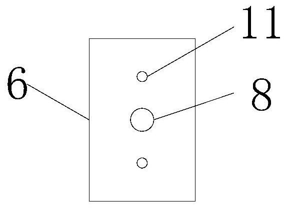
[0027] refer to Figure 1-3 , a kind of engineering monitoring test monitoring equipment, comprising a level body 1 and an installation base 2 that is rotatably connected to the bottom of the level body 1, the bottom of the installation base 2 is provided with a support mechanism for supporting the level body 1, the support mechanism includes a support seat 3, The mounting sleeve 4 that is detachably connected to the top surface of the support base 3, the socket board 5 inserted in the inner cavity of the mounting sleeve 4, and the bearing plate 6 fixedly connected to the top surface of the socket plate 5, the load plate 6 is detachably connected with a protective frame 7, and the protective frame 7 is set under the level body 1, and the mounting sleeve 4 is provided with a fixing piece for fixing the plug-in plate 5; the top surface of the bearing plate 6 is fixedly connected with a threaded column -8, the bottom surface of the mounting base 2 is provided with a threaded groo...
Embodiment 2
[0031] refer to figure 1 with Figure 4 , further defined on the basis of Embodiment 1, the top surface of the support seat 3 is fixedly connected with the connecting cylinder 9 that is fitted with the installation sleeve 4, and the bottom end of the installation sleeve 4 is plugged into the inner cavity of the connection cylinder 9, A bolt 10 for fixing the mounting sleeve 4 is threadedly connected to one end surface of the connecting cylinder 9 .
[0032] In the present invention, through the mutual cooperation of the connecting cylinder 9, the installation sleeve 4 and the bolt 10, the installation sleeve 4 can be installed on the support base 3, the installation sleeve 4 and the support base 3 are easy to disassemble, and the installation sleeve 4 and the support base are avoided. 3. The large overall volume makes storage inconvenient.
Embodiment 3
[0034] refer to Figure 1-3 , further defined on the basis of Embodiment 1, the top surface of the bearing plate 6 and the two sides of the threaded column 8 are fixedly connected with the threaded column 2 11, and the protective frame 7 is provided with a threaded column 8 that is plugged and adapted. Socket one 12, on the protective frame 7 and located on both sides of the socket one 12, there is a socket two 13 that is compatible with the threaded post two 11, and the threaded post one 8 is plugged into the inner cavity of the socket one 12 , the second threaded column 11 is plugged into the inner cavity of the second socket 13, and the second threaded column 11 fixes the protective frame 7 through nuts.
[0035] In the present invention, through the mutual cooperation of the first threaded column 8, the second threaded column 11, the first socket 12 and the second socket 13, the first threaded column 8 is inserted into the first socket 12, and the second threaded column 11...
PUM
 Abstract
Description
Claims
Application Information
 - R&D Engineer
- R&D Manager
- IP Professional
- Industry Leading Data Capabilities
- Powerful AI technology
- Patent DNA Extraction
Browse by: Latest US Patents, China's latest patents, Technical Efficacy Thesaurus, Application Domain, Technology Topic, Popular Technical Reports.
© 2024 PatSnap. All rights reserved.Legal|Privacy policy|Modern Slavery Act Transparency Statement|Sitemap|About US| Contact US: help@patsnap.com


