Non-contact sensor position adjusting structure for measuring shafts

A non-contact, structure-adjusting technology, applied in the direction of supporting machines, mechanical equipment, machine tables/supports, etc., can solve problems such as poor reliability, inaccurate measurement, and measurement failure

Active Publication Date: 2021-05-18
杭州集智机电股份有限公司 +2
View PDF0 Cites 1 Cited by
  • Summary
  • Abstract
  • Description
  • Claims
  • Application Information

AI Technical Summary

Problems solved by technology

[0002] When non-contact measuring sensors are used to measure parameters such as the outer diameter and circular jump of the shaft, the installation position of the sensor is closely related to the measurement accuracy. Generally, the measurement path of the sensor must pass through the axis of the shaft, that is, the center of the section, otherwise it will lead to incorrect measurement. accurate, resulting in measurement failure
At this stage, there is no mature solution to this kind of problem. Generally, manual adjustment is used for adjustment, or machining is used to ensure the accuracy of the installation position, which leads to low measurement accuracy and poor reliability.

Method used


Image

  • Non-contact sensor position adjusting structure for measuring shafts
  • Non-contact sensor position adjusting structure for measuring shafts
  • Non-contact sensor position adjusting structure for measuring shafts

Examples


Embodiment Construction

[0023] The technical solutions of the present invention will be further fully and clearly described below in conjunction with the accompanying drawings and specific embodiments.

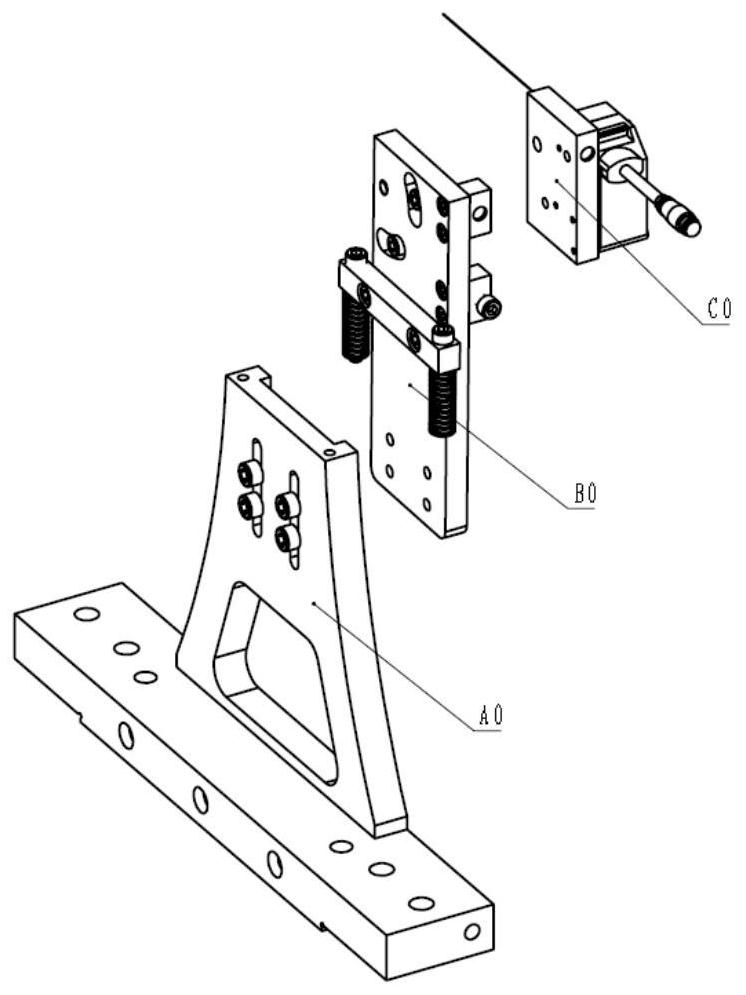
[0024] Such as figure 1 As shown, the present invention includes the equipment measurement reference, and also includes a fixed assembly A0, a translation assembly B0 and a rotation assembly C0, the fixed assembly A0 is fixedly installed on the equipment measurement reference, and the translation assembly B0 can be adjusted up and down and fixed on the fixed assembly A0 , the rotation assembly C0 can be relatively rotatably installed on the translation assembly B0.

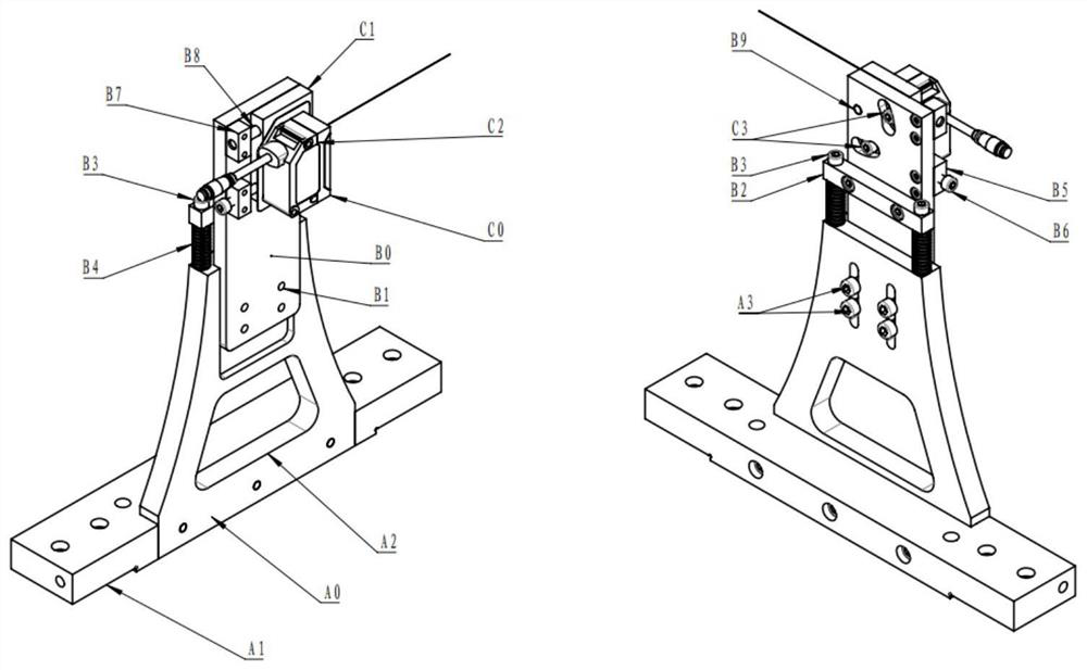
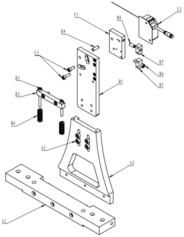
[0025] Such as figure 2 and image 3 As shown, the fixing assembly A0 includes a measuring mechanism base A1, a main body bracket A2 and a first screw A3. The measuring mechanism base A1 is fixedly installed on the equipment measurement reference, and the main body bracket A2 is fixedly installed on the measuring mechanism base A1.

...


PUM


Abstract

The invention discloses a sensor position adjusting mechanism for non-contact measurement of shaft parts. The sensor position adjusting mechanism for non-contact measurement of the shaft parts comprises an equipment measuring basis, a fixing assembly, a translation assembly and a rotating assembly, wherein the fixing assembly is fixedly installed on the equipment measuring basis; the translation assembly is installed and fixed on the fixing assembly in an up-down lifting adjustment mode; and the rotating assembly is installed on the translation assembly in a relatively rotating mode. According to the sensor position adjusting mechanism for non-contact measurement of the shaft parts provided by the invention, two adjustments of translation and rotation are alternately used, so that the final error can be converged to a relatively small value, and high-precision adjustment of a measurement point is realized; and the structure provided by the invention is beneficial to reducing the process requirements on processing and assembling, and is easy to popularize.

Description

technical field [0001] The invention relates to a sensor position adjustment mechanism, in particular to a non-contact sensor position adjustment structure of a measuring shaft. Background technique [0002] When non-contact measuring sensors are used to measure parameters such as the outer diameter and circular jump of the shaft, the installation position of the sensor is closely related to the measurement accuracy. Generally, the measurement path of the sensor must pass through the axis of the shaft, that is, the center of the section, otherwise it will lead to incorrect measurement. accurate, resulting in measurement failure. At this stage, there is no mature solution to this kind of problem. Generally, manual adjustment is used for adjustment, or machining is used to ensure the accuracy of the installation position, which leads to low measurement accuracy and poor reliability. Contents of the invention [0003] In order to solve the deficiency of the background techno...

Claims


Application Information

Patent Timeline
IPC IPC(8): F16M11/04F16M11/06F16M11/18F16M11/22
CPCF16M11/046F16M11/06F16M11/18F16M11/22
Inventor 谢轩武振宇彭凯隆余振平高景衡
Owner 杭州集智机电股份有限公司
Why Eureka
Try Eureka