Flow path switching valve

A flow path switching and valve shaft technology, applied in valve details, valve devices, multi-port valves, etc., to solve problems such as difficulty in managing the inclination of welded shells and complex shapes of shells

Active Publication Date: 2021-05-18
FUJIKOKI MFG CO LTD +1
View PDF5 Cites 0 Cited by
  • Summary
  • Abstract
  • Description
  • Claims
  • Application Information

AI Technical Summary

Problems solved by technology

However, since the housing rotatably supports the valve shaft and accommodates the rotation drive unit, the housing has a complicated shape.
Therefore, it is difficult to manage the inclination of the casing during welding with the conventional flow path switching valve.

Method used


Image

  • Flow path switching valve
  • Flow path switching valve
  • Flow path switching valve

Examples


Embodiment Construction

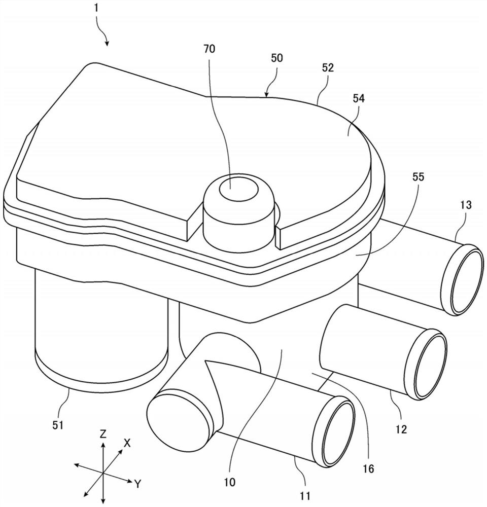
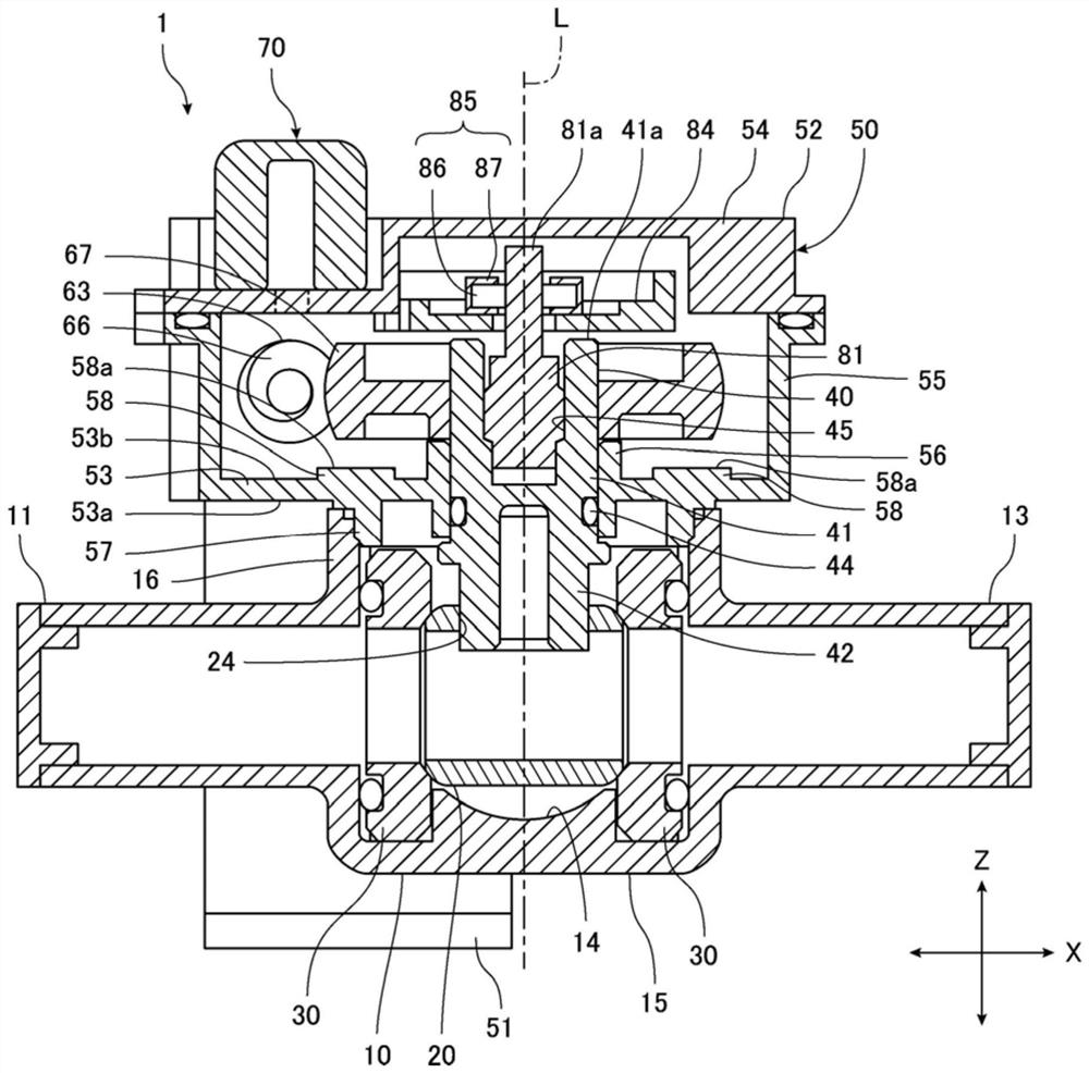
[0026] Below, refer to Figure 1 to Figure 8 A channel switching valve according to an embodiment of the present invention will be described.

[0027] figure 1 It is a perspective view of a channel switching valve according to an embodiment of the present invention. figure 2 yes figure 1 Left side view of the flow switching valve. image 3 yes figure 1 A cross-sectional view (longitudinal cross-sectional view) along the rotation axis of the ball valve core in the flow path switching valve. Figure 4 yes figure 1 The flow path switching valve has a top view of the valve body. exist Figure 4 In the valve chamber of the valve body, a ball valve core and a valve seat part are arranged. Figure 5 yes means figure 1 A plan view of the state where the upper wall portion of the gear box is removed of the channel switching valve of FIG. Figure 6 It is a plan view showing a state in which the rotation position detection unit is further removed. Figure 7 It is a plan view ...


PUM


Abstract

Provided is a flow path switching valve having a structure capable of easily managing the inclination of a housing during fusion welding. In a flow path switching valve (1), a valve shaft (40) attached to a ball valve element (20) is disposed across a valve body (10) and a gearbox (52). A driving part (60) for driving the ball valve element (20) to rotate through the valve shaft (40) is provided with a large-diameter gear (67) installed on a cylindrical part (41) of the valve shaft (40). The gearbox (52) has a bottom wall part (53) disposed so as to close the opening of the valve body (10); a bearing part (56) provided on the bottom wall part (53) and rotatably supporting the valve shaft (40); and a flat surface part (58a) provided on the inner surface (53b) of the bottom wall part (53) so as to correspond to the peripheral wall part (16) of the valve body (10).

Description

technical field [0001] The invention relates to a flow path switching valve. In particular, the present invention relates to a flow path switching valve in which a valve main body housing a valve body and a housing housing a drive unit for driving the valve body are joined by welding. Background technique [0002] Patent Document 1 discloses an example of a conventional channel switching valve. This channel switching valve has a valve main body having a valve chamber, a spherical valve body disposed in the valve chamber, and a valve shaft connected to the valve body. The channel switching valve has a rotary drive unit including a motor and a drive gear, and a case that accommodates the rotary drive unit. The rotation drive unit rotates the valve body via the valve shaft. [0003] prior art literature [0004] patent documents [0005] Patent Document 1: Japanese Patent Laid-Open No. 2018-115691 [0006] The technical problem to be solved by the invention [0007] Such...

Claims


Application Information

Patent Timeline
IPC IPC(8): F16K11/087F16K27/06F16K27/10F16K31/04F16K31/53
CPCF16K11/087F16K27/067F16K27/107F16K31/043F16K31/535
Inventor 近藤大介望月健一高桥恒吏
Owner FUJIKOKI MFG CO LTD
Why Eureka
Try Eureka