Speed change device and gearbox
A technology of speed change device and cone wheel, which is applied in the direction of transmission device, friction transmission device, transmission device control, etc., and can solve the problems of unbalanced torque transmission reliability and cost
- Summary
- Abstract
- Description
- Claims
- Application Information
AI Technical Summary
Problems solved by technology
Method used
Image
Examples
Embodiment 1
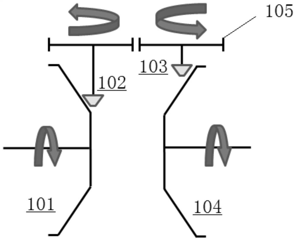
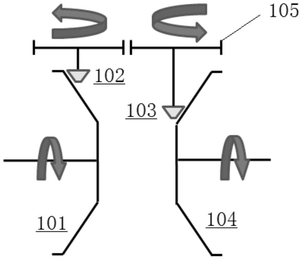
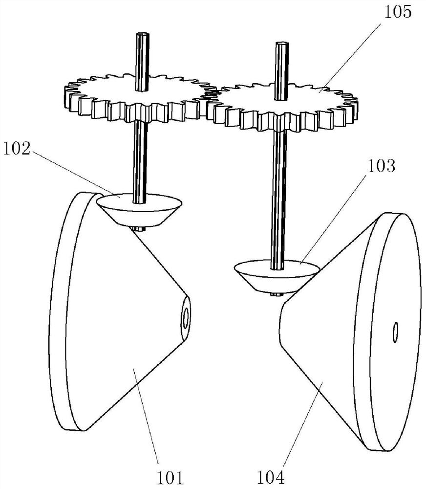
[0066] a transmission device such as figure 1 -3, it includes a driving cone 101, a first driving cone 102, a driven cone 103, a second driving cone 104 and a transmission mechanism 105.
[0067] Wherein the driving cone 101 rotates at a set input speed, the first driving cone 102 contacts and drives the driving cone 101, the second driving cone 104 contacts and drives the driven cone 103, and the first driving cone 102 passes through The transmission mechanism 105 is connected with the second transmission cone 104, wherein the axis of the first transmission cone 102 is perpendicular to the axis of the driving cone 101, and the axis of the second transmission cone 104 is perpendicular to the axis of the driven cone 103. between vertical, such as figure 1 shown;
[0068] Further, the axis of the driving cone 101 and the axis of the driven cone 103 are collinear (coaxial).
[0069] The transmission mechanism 105 in this embodiment can be a gear transmission group, also can be...
Embodiment 2
[0076] This embodiment provides a transmission, such as Figure 4 -9, including input shaft 201, output shaft 202, driving cone 203, more than two first driving cones 204, driven cone 205, more than two second driving cones 206 and more than two The transmission mechanism 207, wherein the first transmission cone wheel 204, the second transmission cone wheel 206 and the transmission mechanism 207 have the same number and one-to-one correspondence.
[0077] In this embodiment, for example, eight first transmission bevel wheels 204 and eight second transmission bevel wheels 206 are provided, wherein the eight first transmission bevel wheels 204 are arrayed around the axis of the driving cone 203, and the eight second transmission bevel wheels The cone wheel 206 is arrayed around the axial direction of the driven cone 205, based on the same principle as in Embodiment 1, combined with Figure 7 , 8 As shown, by adjusting the contact position between the first driving bevel 204 an...
Embodiment 3
[0093] This embodiment provides a transmission, such as Figure 10 As shown, the difference between this embodiment and Embodiment 2 is that the first screw rod is replaced by the first speed-regulating slider 301 with end thread in the transmission mechanism, so that the first speed-regulating slider 301 and the first An end thread pair is formed between the frames 302 , and the second screw mandrel is replaced with a second speed regulating slider 303 with end threads, and an end thread pair is formed between the second speed regulating slider 303 and the second frame 304 .
PUM
 Abstract
Description
Claims
Application Information
 - R&D Engineer
- R&D Manager
- IP Professional
- Industry Leading Data Capabilities
- Powerful AI technology
- Patent DNA Extraction
Browse by: Latest US Patents, China's latest patents, Technical Efficacy Thesaurus, Application Domain, Technology Topic, Popular Technical Reports.
© 2024 PatSnap. All rights reserved.Legal|Privacy policy|Modern Slavery Act Transparency Statement|Sitemap|About US| Contact US: help@patsnap.com


