Eureka AIR delivers breakthrough ideas for toughest innovation challenges, trusted by R&D personnel around the world.

Bridge pier stud bent cap formwork system and construction method

A bridge and system technology, applied in the direction of bridges, bridge construction, bridge parts, etc., can solve problems such as low safety, many safety threats, materials, personnel, and large investment

Active Publication Date: 2021-05-18
安徽仁成建设工程有限公司
View PDF5 Cites 0 Cited by
  • Summary
  • Abstract
  • Description
  • Claims
  • Application Information

AI Technical Summary

Problems solved by technology

Due to the limited space of urban overpasses, there are often line crossings. The terrain of bridges in mountainous areas is rugged and the geological conditions are different. , personnel, great investment
[0004] The hoop support method is suitable for the construction of round pier column cap beams with large heights or poor foundations. However, for the case of huge cap beam structures, the conventional hoop support method also has obvious shortcomings. Since the hoop is without a floor support, the entire support Generally, there are large truss main beams and a large number of steel secondary beams. The installation and removal of the brackets requires a lot of high-altitude lifting operations and mechanical shifts, which poses many safety threats. In addition, the weight of the hoop is large and the number of bolts is large. Installation Inconvenient to remove

Method used


Image

  • Bridge pier stud bent cap formwork system and construction method
  • Bridge pier stud bent cap formwork system and construction method
  • Bridge pier stud bent cap formwork system and construction method

Examples


Embodiment Construction

[0045] The following is attached Figure 1-4 The application is described in further detail.

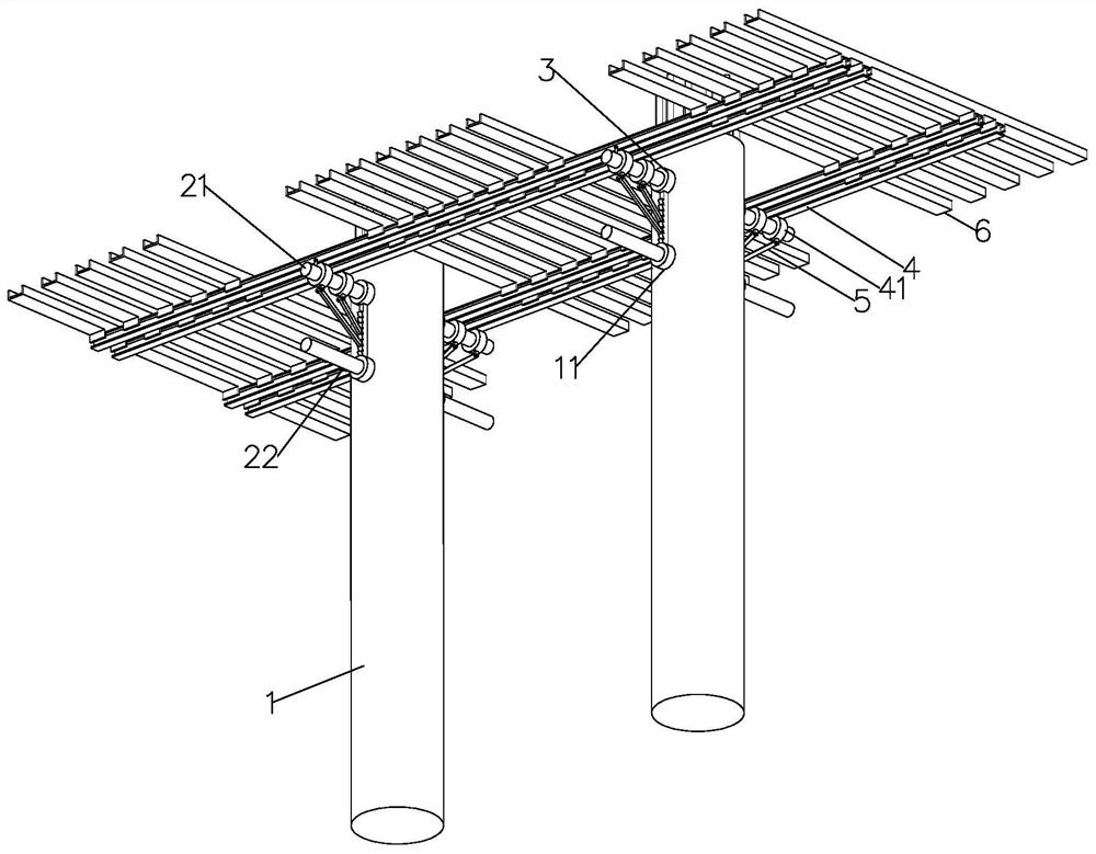
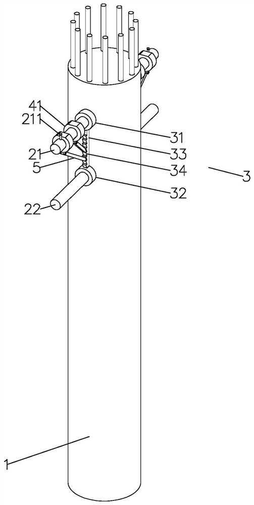
[0046] The embodiment of the present application discloses a cover beam formwork support system based on bridge pier columns. refer to figure 1, the cover beam formwork system includes a pier column 1, and the pier column 1 is used as a supporting base. The bridge in this embodiment includes two pier columns 1, both of which are cylinders, and are set at the same height; the upper part of the pier column 1 is close to There are two perforations 11 at the position of the top. The axial directions of the two perforations 11 are parallel, and the upper and lower positions are opposite. They all pass through the central axis of the pier column 1. The axial direction is perpendicular to the plane where the axes of the two piers 1 are located.

[0047] A crossing strut is installed on the pier 1, and the crossing strut includes an upper strut 21 and a lower strut 22 with the same diamet...


PUM


Abstract

The invention relates to the field of bridge construction, and particularly relates to a bridge pier stud bent cap formwork system and a construction method. The bridge pier stud bent cap formwork system comprises a pier stud, at least two groups of transversely penetrating supporting rods transversely penetrating through the pier stud, a supporting frame laid on the transversely penetrating supporting rods and a bent cap mold mounted on the supporting frame; each transversely penetrating supporting rod comprises an upper supporting rod and a lower supporting rod which are vertically opposite, the upper supporting rod and the lower supporting rod are parallel and transversely penetrate through the pier column, the ends of the upper supporting rod and the lower supporting rod stretch out, and an auxiliary supporting frame is connected between the upper supporting rod and the lower supporting rod; the supporting frame comprises a main cross beam frame connected to the same ends of the at least two upper supporting rods, an auxiliary supporting rod is connected to the main cross beam frame, and the lower end of the auxiliary supporting rod is connected to an auxiliary supporting frame; and the number of the main cross beam frames connected to the two ends of the upper supporting rod is the same, a reinforcing rod is connected between the main cross beam frames, and the cover beam mold is installed on the main cross beam frames and the reinforcing rod. The formwork structure of the bent cap is optimized, and the installation difficulty of a formwork system is reduced.

Description

technical field [0001] The application relates to the field of bridge construction, in particular to a bridge pier column cap beam formwork support system and a construction method. Background technique [0002] The bridge pier column is the lower load-bearing object used to carry the upper structure of the bridge. The bridge cover beam is constructed on the bridge pier column to support the upper structure of the bridge and transfer all the load to the lower structure. Both are important in bridge engineering. Its structural design and quality management have a profound impact on the overall construction quality and stability of the bridge. [0003] There are two main types of formwork support for cover beam construction: floor support and non-floor support. The non-floor support is not erected by the ground, but a suspended formwork support that is erected by using the poured pier column structure to form a corbel near the top of the pier column. Buried steel plate metho...

Claims


Application Information

Patent Timeline
Patent Type & Authority Applications(China)
IPC IPC(8): E01D19/02E01D21/00
CPCE01D19/02E01D21/00Y02A30/60
Inventor 李玉龙尹佳余伟翟敏吴雪桂笑娜吴连为
Owner 安徽仁成建设工程有限公司
Why Eureka
Eureka Blog
Learn More