
Jet loop reactor for preparing ethylene through oxidative coupling of methane

A loop reactor, oxidative coupling technology, applied in chemical instruments and methods, chemical/physical processes, etc., can solve the problems of low ethylene yield, serious back-mixing, and uneven temperature distribution

Active Publication Date: 2021-05-18
山西潞安化工有限公司 +1
View PDF15 Cites 2 Cited by
  • Summary
  • Abstract
  • Description
  • Claims
  • Application Information

AI Technical Summary

Problems solved by technology

[0007] In order to overcome the deficiencies of the above-mentioned prior art, the present invention provides a jet loop reactor for the oxidative coupling of methane to ethylene to solve the problems of uneven temperature distribution in the reactor, serious back-mixing, and low ethylene yield

Method used


Image

  • Jet loop reactor for preparing ethylene through oxidative coupling of methane
  • Jet loop reactor for preparing ethylene through oxidative coupling of methane

Examples


Embodiment 1

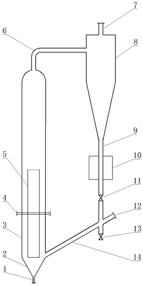
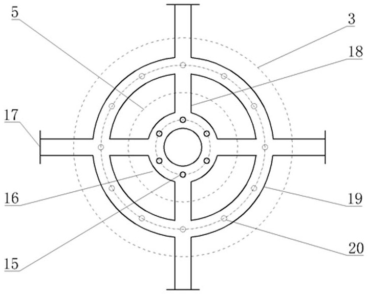
[0027]An injection annular reactor for methane oxidation occlusion, is divided into a conical bottom region, a circulation region, a gas-solid separation zone, a cyclone separation zone, and a return zone. The tapered bottom region includes nozzle 1 and cone bottom 2; the circulation region includes a lower space, a gas distributor 4, and a guide cylinder 5 in the casing 3; the gas-solid separation zone includes the upper space of the housing 3; the cyclone separation zone includes a cyclone separation A device 8; the return zone comprises the leg 9, the heat exchanger 10, the retainer 11, the secondary wind inlet 12, the discharge valve 13, and the return tube 14.

[0028]Such asfigure 1 As shown, the nozzle 1 is located at the bottom of the conical bottom 2, and the tapered bottom 2 is located at the bottom of the housing 3, and the guide cylinder 5 is placed in the lower portion of the housing 3, and the gas distributor 4 is transverse to the housing 3 and its vertical center line a...

Embodiment 2

[0032]Unlike Example 1, the catalyst has an average particle diameter of 100 μm, and the reaction temperature is 850 ° C, at an attenuated operation, the gas component of the nozzle is mainly methane, and the gas component of the gas distributor and the secondary venting air is mainly Oxygen and nitrogen, volume vacuum rate is 8000 h-1, Methane: oxygen: Nitrogen molar ratio is 3: 1: 1, the methane conversion is 47%, and the ethylene yield is 31%.

Embodiment 3

[0034]Unlike Example 1, the average particle diameter of the catalyst is 150 μm, the reaction temperature is 800 ° C, the operating pressure is 5 bar, and the gas components passing through the nozzle are mainly methane and oxygen, through the gas distributor and the secondary venting air. The gas component is mainly oxygen and nitrogen, the volume vacant is 6000 h-1, Methane: oxygen: Nitrogen molar ratio is 3: 1: 1, the methane conversion is 46%, and the ethylene yield is 27%.


PUM


Abstract

The invention relates to the technical field of methane conversion, in particular to a jet loop reactor for preparing ethylene through oxidative coupling of methane. The jet loop reactor comprises a nozzle, a conical bottom, a guide cylinder, a shell, a gas distributor, a cyclone separator, a heat exchanger and a material returning device, the nozzle is positioned at the bottom of the conical bottom, the conical bottom is positioned at the bottom of the shell, the guide cylinder is arranged in the shell and is positioned at the lower part, the gas distributor transversely penetrates through the shell, and the vertical center line of the gas distributor coincides with the center line of the guide cylinder; a shell top end gas outlet is formed in the top end of the shell and is communicated with the upper part of a cyclone separator (8). The nozzle, the conical bottom, the guide cylinder and the gas distributor are utilized to form forced internal circulation of materials, regular movement of the materials can be promoted, backmixing is reduced, mass transfer and heat transfer are enhanced, uniform distribution of the temperature in the reactor is facilitated, and the catalyst utilization rate and the product yield are improved.

Description

Technical field[0001]The present invention relates to the field of methane conversion techniques, and more particularly to a jet circular reactor for methane oxidation occlusion.Background technique[0002]Ethylene is an important foundation organic chemical product and raw material, and its production level is an important indicator of a national chemical strength. At present, ethylene production is based on naphtha, there is a cost, high energy consumption and greenhouse gas emissions. With the development of the international economy, ethylene production raw materials tend to lightly and diversified. Methane oxidation coupling (OCM) one-step directly has an advantage of simple route, good economic, and is a broad ethylene production technology, which is of great significance for my country's energy structure optimization.[0003]The OCM reaction was a strong reflection reaction under high temperature (750 ~ 950 ° C), and the ethylene yield was high in temperature. How to remove drama...

Claims


Application Information

Patent Timeline
IPC IPC(8): B01J8/08
CPCB01J8/082B01J8/085
Inventor 李德宝高用祥刘俊义林明桂马军祥张力贾丽涛崔艳斌余海兵栗鑫
Owner 山西潞安化工有限公司
Learn More