Tool rest cooling structure for machine tool

A technology of cooling structure and tool holder, applied in metal processing machinery parts, maintenance and safety accessories, metal processing equipment, etc., can solve the problem of poor stability of metal hose or plastic Pipe or plastic pipe bending and other problems, to achieve the effect of reducing workload, simple structure and avoiding deformation and dislocation

Pending Publication Date: 2021-05-14
宁波品上精密机床有限公司
View PDF0 Cites 0 Cited by
  • Summary
  • Abstract
  • Description
  • Claims
  • Application Information

AI Technical Summary

Problems solved by technology

However, in order not to affect the movement of the tool holder and the installation of the tool on the tool holder, the metal hose or plastic tube needs to go around above the tool holder, so that the metal hose or plastic tube needs to be bent, and the installation is troublesome and the stroke is long. , the cost is high. In addition, during use, due to the rapid ejection of high-pressure cutting fluid, the pressure on the metal hose or plastic pipe is relatively high, and the problem of deformation and misalignment is easy to occur during use, so that the ejected high-pressure cutting fluid It cannot be aligned with the tool head of the prop, so that the purpose of cooling and blowing away waste chips cannot be achieved, and the position needs to be adjusted frequently, which increases the operator's operating burden. At the same time, metal hoses or plastic pipes with long strokes are less stable , easy to shake during use, which also affects the performance of the machine tool

Method used


Image

  • Tool rest cooling structure for machine tool
  • Tool rest cooling structure for machine tool
  • Tool rest cooling structure for machine tool

Examples


Embodiment Construction

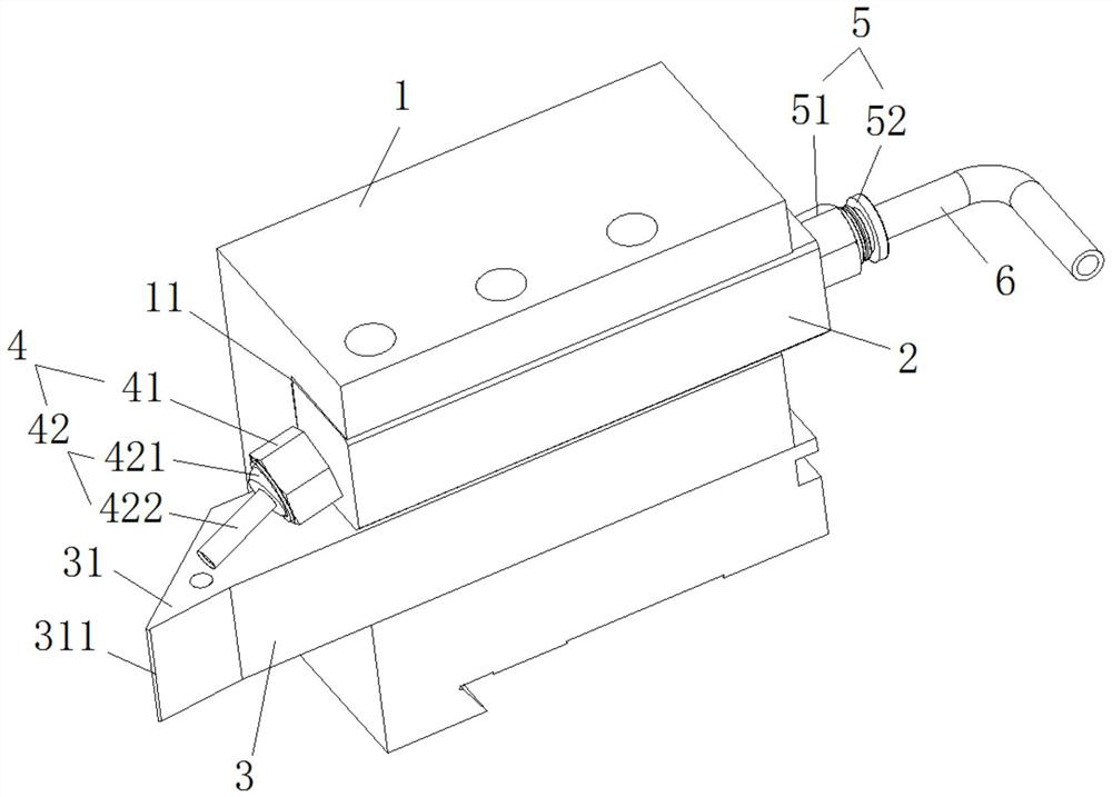
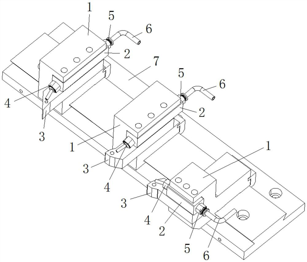
[0021] In order to make it easy to understand the technical means, creative features, goals and effects achieved by the present invention, the following examples are combined with the appended figure 1 to attach image 3 The technical solutions provided by the present invention are described in detail, but the following content is not intended as a limitation of the present invention.

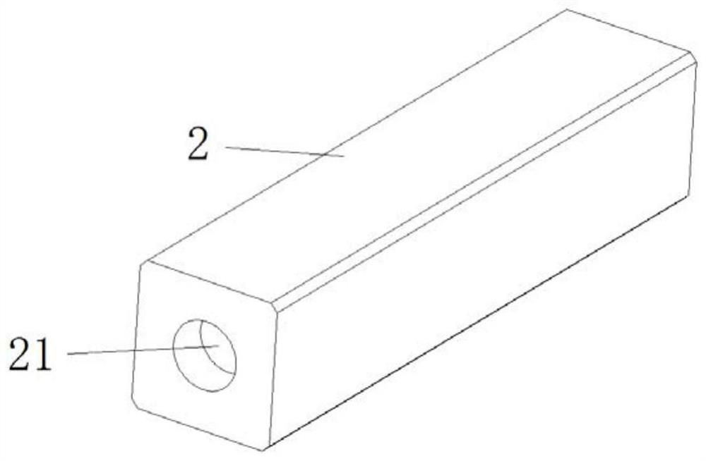
[0022] figure 1 It is a structural diagram of an embodiment of a tool post cooling structure for a machine tool of the present invention; figure 2 It is a structural diagram of a tool press block in a cooling structure of a tool holder for a machine tool according to the present invention. Such as figure 1 and figure 2 As shown, the tool rest cooling structure for machine tools provided by this embodiment includes: a tool seat 1 and a presser block 2. At this time, the tool seat 1 is provided with a tool mounting groove 11, and several connecting tool mounting grooves are provided on the ...


PUM


Abstract

The invention provides a tool rest cooling structure for a machine tool, and belongs to the technical field of machine tool machining. According to the tool rest cooling structure for the machine tool, a flow guide hole penetrating through the two ends and a nozzle and a connection joint which are arranged at the two ends of the flow guide hole are formed in a cutter pressing block; the connection joint is connected with a cutting fluid feeding pipe; a spray head of the nozzle faces a cutter head of a cutter; the existing cutter pressing block structure is fully used as a conveying pipeline, cooling of a machined position and blowing-away operation of sweeps are achieved, cost is reduced, the conveying stroke of cutting fluid is only the width of a tool apron within the range of the tool apron, and the conveying stroke is shortened; and meanwhile, the pressure bearing capacity is better, pipeline bending is not needed, the deformation and dislocation problems are avoided, the structural strength is higher, the shaking problem in the using process is avoided, stability is better, adjustment only needs to be conducted once in the initial installation process, the problems of inconvenience and heavy workload caused by subsequent repeated adjustment are avoided, the arrangement space is saved, the installation limitation is small, the adaptability is higher, and the use performance of the machine tool is improved easily.

Description

technical field [0001] The invention relates to the technical field of processing machine tools, in particular to a tool holder cooling structure for machine tools. Background technique [0002] Processing machine tools include a series of equipment such as lathes, milling machines, and machining centers. As common equipment for product processing, the rationality of its structure is a necessary condition to ensure the performance of processing machine tools. [0003] At present, after the tool holders of traditional machine tools on the market are installed and during the processing process, in order to prevent the problems of excessive temperature and waste entanglement, it is necessary to pass high-pressure cutting fluid on the frame through metal hoses or plastic pipes. Guided to the cutter head and sprayed out to achieve the purpose of cooling and blowing away waste. However, in order not to affect the movement of the tool holder and the installation of the tool on the...

Claims


Application Information

Patent Timeline
Patent Type & Authority Applications(China)
IPC IPC(8): B23Q11/10B23Q11/00
CPCB23Q11/005B23Q11/10
Inventor 陈圣杰姜少飞陈奕杭童晨屹
Owner 宁波品上精密机床有限公司
Why Eureka
Try Eureka