
Power supply equipment, planar transformer and manufacturing method of planar transformer

A technology for planar transformers and manufacturing methods, which is applied to transformer/inductor components, transformer/inductor coils/windings/connections, circuits, etc., can solve the problems of high scrap rate and low transformer production efficiency, and achieve production efficiency improvement , less assembly process, save the effect of assembly and welding steps

Pending Publication Date: 2021-05-11
济南安海半导体有限公司
View PDF1 Cites 2 Cited by
  • Summary
  • Abstract
  • Description
  • Claims
  • Application Information

AI Technical Summary

Problems solved by technology

[0005] In view of the deficiencies of the above-mentioned prior art, the object of the present invention is to provide a power supply device, a planar transformer and a manufacturing method thereof, so as to solve the problems of low production efficiency and high scrap rate of existing transformers

Method used


Image

  • Power supply equipment, planar transformer and manufacturing method of planar transformer
  • Power supply equipment, planar transformer and manufacturing method of planar transformer
  • Power supply equipment, planar transformer and manufacturing method of planar transformer

Examples


Embodiment Construction

[0024]In order to make the objectives, technical solutions and advantages of the present invention, the present invention will be described in further detail below with reference to the accompanying drawings and examples. It should be understood that the specific embodiments described herein are merely intended to illustrate the invention and are not intended to limit the invention.

[0025]It should be noted that when the component is referred to as "mounting", "fixed to" or "set" on another component, it can be directly in another component or may simultaneously present. When a component is called "connected to" another component, it can be directly connected to another component or may always exist in central components.

[0026]It will also be noted that the left, right, upper, and lower orientation of the embodiments of the present invention are merely relative concepts or referenced in the normal use of the product, and should not be considered as limiting. .

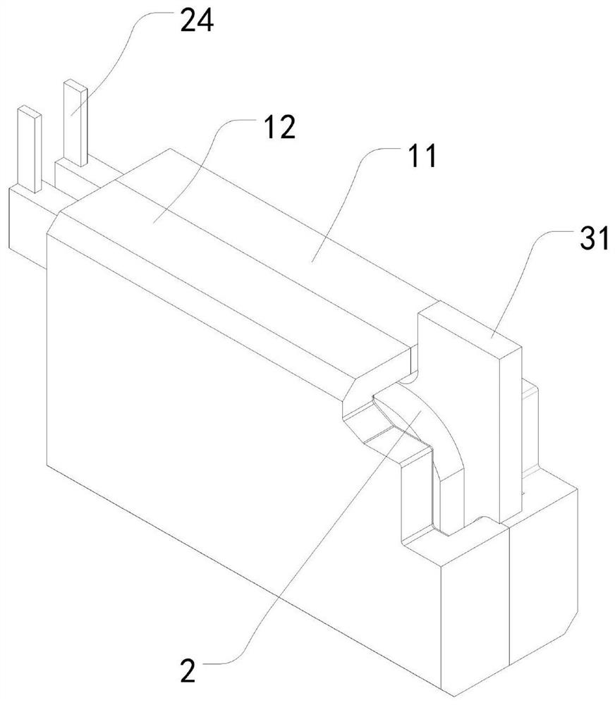
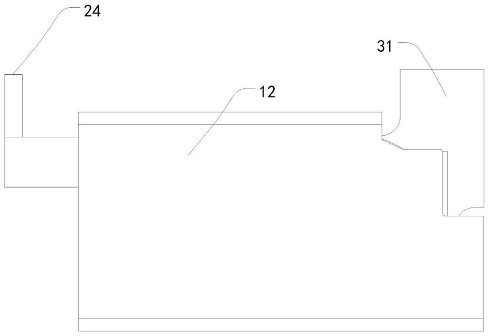
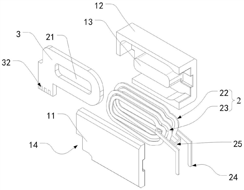
[0027]Seefigure 1 ,figur...


PUM

PropertyMeasurementUnit
thicknessaaaaaaaaaa
thicknessaaaaaaaaaa

Abstract

The invention discloses power supply equipment, a planar transformer and a manufacturing method of the planar transformer. The planar transformer comprises a first magnetic core, a first secondary coil, a PCB coil, a second secondary coil and a second magnetic core which are sequentially arranged, the first secondary coil and the second secondary coil are each provided with a first pin and a secondary wiring pin, and insulating paint layers are arranged outside the first secondary coil and the second secondary coil. The first pin and the secondary wiring pin are conductive pins. According to the invention, the insulating paint layers are arranged outside the first secondary coil and the second secondary coil, the secondary coil is wrapped by the insulating paint in a paint dipping mode, the phenomenon that a copper exposed area is broken down by overhigh voltage is avoided, and the insulating paint layers are thinner than epoxy resin, so that it is facilitated that the planar transformer is ultrathin.

Description

Technical field[0001]The present invention relates to a small inductive transformer technique, and more particularly to a power supply device and a planar transformer and a method of making it.Background technique[0002]Compared with conventional transformers, the magnetic core size is large, especially the height reduction, which has a considerable attraction to the power supply (such as charger) in a strict restriction in space, so that Become a preferred magnetic component in many power supplies.[0003]As: CN209015849U, the name is: a new type of charger transformer, discloses the transformer includes the left and right cores, the left and right secondary coils, and the PCB coil between the secondary coils. During the production process, two gums were required after the secondary coil stamping, and the first inclination was mainly used to fill the slit between the secondary coil, the second injection is plastic in the secondary coil. Oxygen resin, it can be seen that the process of...

Claims


Application Information

Patent Timeline
Patent Type & Authority Applications(China)
IPC IPC(8): H01F27/32H01F27/30
CPCH01F27/306H01F27/32H01F27/323
Inventor 黄昕曾昭雄陈杰
Owner 济南安海半导体有限公司
Learn More