
Axial-flow type pressure reduction assembly and axial-flow type gradual change pressure reduction valve internal part structure

A technology of axial-flow and pressure-reducing valves, which is applied to the valve shell structure, valve details, valve devices, etc., can solve the problems of long production cycle, large damage to the inner wall of the valve, and uncontrollable hazards of increased valve leakage, and achieve the goal of dismantling It is convenient for installation and maintenance, protects the inner wall of the valve, and improves the service life

Pending Publication Date: 2021-05-11
WUXI SMART AUTO CONTROL ENG CO LTD
View PDF0 Cites 0 Cited by
  • Summary
  • Abstract
  • Description
  • Claims
  • Application Information

AI Technical Summary

Problems solved by technology

The labyrinth structure uses the labyrinth channel on the labyrinth sheet to change the flow direction of the medium multiple times to consume energy and finally achieve the purpose of reducing pressure; firstly, the processing of the labyrinth channel is complicated, the production cycle is long, and the delivery cycle cannot be met. Shorter customers, secondly, the labyrinth components are difficult to disassemble and maintain, and special tooling is required. Finally, the fluid flowing out of the labyrinth channel directly scours the inner wall of the valve, which will cause relatively large damage to the inner wall of the valve.
The radial decompression hole structure is to decompose the concentrated single total energy into many small energy units by processing holes on the radial cylinder wall and decomposing the larger jet fluid into many small streams. , consume energy through multiple small pressure-reducing holes, and finally achieve the purpose of reducing pressure; although the radial pressure-reducing hole is simple to process, its structure is doomed to be unable to design different levels of pressure-reducing according to working conditions, and it also has The danger of direct erosion of the inner wall of the valve by the labyrinth structure increases the uncontrollable harm of the leakage of the valve
It can be concluded that the above two traditional structures cannot achieve the effect of low cost and precise control of voltage reduction

Method used


Image

  • Axial-flow type pressure reduction assembly and axial-flow type gradual change pressure reduction valve internal part structure
  • Axial-flow type pressure reduction assembly and axial-flow type gradual change pressure reduction valve internal part structure
  • Axial-flow type pressure reduction assembly and axial-flow type gradual change pressure reduction valve internal part structure

Examples


Embodiment Construction

[0022] It should be noted that, in the case of no conflict, the embodiments of the present invention and the features in the embodiments can be combined with each other. The present invention will be described in detail below with reference to the accompanying drawings and examples.

[0023] In order to enable those skilled in the art to better understand the solutions of the present invention, the following will clearly and completely describe the technical solutions in the embodiments of the present invention in conjunction with the accompanying drawings in the embodiments of the present invention. Obviously, the described embodiments are only Embodiments of some, but not all, embodiments of the present invention. Based on the embodiments of the present invention, all other embodiments obtained by persons of ordinary skill in the art without making creative efforts shall fall within the protection scope of the present invention.

[0024] It should be noted that the terms "f...


PUM


Abstract

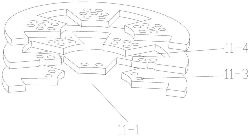
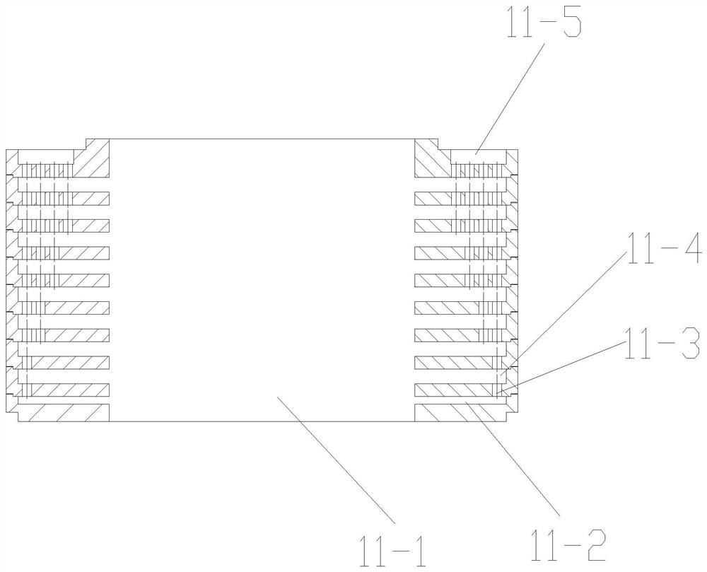
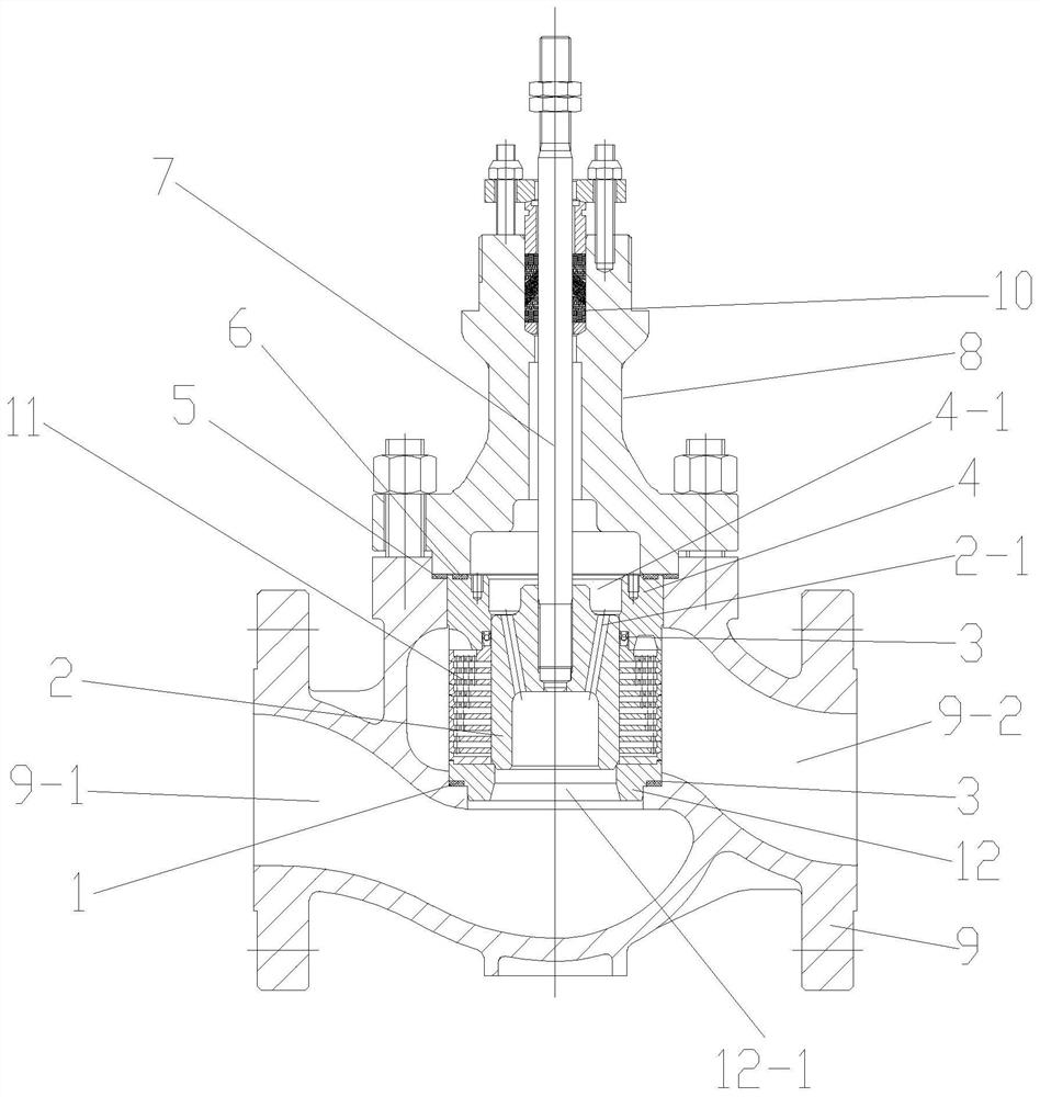
The invention relates to an axial-flow type pressure reduction assembly and an axial-flow type gradual change pressure reduction valve internal part structure. A valve element hole is formed in the middle of the assembly, a drainage groove is formed in the lower portion of the center of the assembly and communicated with the valve element hole, pressure reduction holes and pressure reduction grooves are sequentially formed in the upper portion of the drainage groove at intervals, and a liquid outlet is formed in the upper portion of the assembly and communicated with the pressure reduction hole or the pressure reduction groove in the uppermost layer. The axial-flow type pressure reduction assembly and the axial-flow type gradual change pressure reduction valve internal part structure have the advantages of effectively reducing pressure, preventing cavitation corrosion, reducing valve noise, reducing vibration, being convenient, reliable, easy to maintain, long in service life and the like, and are suitable for a special high-pressure-difference process control process. The axial-flow type pressure reduction assembly and the axial-flow type gradual change pressure reduction valve internal part structure are convenient to disassemble, assemble and maintain, a special disassembly tool does not need to be designed, a special pneumatic or hydraulic auxiliary tool does not need to be provided for disassembly and assembly of the axial-flow type pressure reduction assembly, meanwhile, compared with complex labyrinth flow channel machining, the pressure reduction holes distributed in the axial direction can be achieved only through simple turning and drilling, a machining center is not needed, the machining cost is low, the equipment utilization rate is high, and the harsh delivery cycle can be met.

Description

technical field [0001] The invention belongs to the technical field of valves, in particular to an axial-flow pressure-reducing component and an axial-flow gradual-change pressure-reducing valve trim structure. Background technique [0002] In devices such as atmospheric and vacuum distillation, delayed coking, hydrocracking, hydrofinishing, catalytic cracking, sulfur recovery, etc., there are often working conditions with high pressure difference. With the emergence of high pressure differential conditions, it will definitely bring destructive factors that endanger the use of valves, such as flashing, cavitation, and noise. Their appearance will damage the valve trim and the inner wall of the valve. The pressure of liquid with high pressure difference flowing through the throttling part of the pipeline will be higher or lower than the vapor pressure (PV), which will cause cavitation or flashing, and the noise is derived from the shear stress in the fluid turbulence; the tra...

Claims


Application Information

Patent Timeline
Patent Type & Authority Applications(China)
IPC IPC(8): F16K47/08F16K27/08
CPCF16K27/08F16K47/08
Inventor 陆坤铭张从礼徐晓禹顾乐乐陈洋
Owner WUXI SMART AUTO CONTROL ENG CO LTD
Learn More