
Guide rail adjusting device

A technology of adjusting device and guide rail, applied in the field of guide rail adjustment, can solve the problems of die offset, inability to guarantee the accuracy of up and down movement, and inability to guarantee product quality, etc.

Pending Publication Date: 2021-05-11
FUHUA ZHONGYUAN JIANGSU HEAVY MACHINERY TECH CO LTD
View PDF0 Cites 1 Cited by
  • Summary
  • Abstract
  • Description
  • Claims
  • Application Information

AI Technical Summary

Problems solved by technology

[0002] For the pressing of the die, it is often necessary to use a carriage to drive the die to press down. Most of the existing carriages use cylindrical carriages, which are similar to oil cylinders. However, after long-term use, the carriages will wear out, resulting in slippage. There will be a gap between the frames, and then the die will shift when sliding, and the accuracy of the up and down movement cannot be guaranteed, resulting in product quality that cannot be guaranteed

Method used


Image

  • Guide rail adjusting device

Examples


Embodiment Construction

[0012] The present invention is described in further detail now in conjunction with accompanying drawing. The drawings are all simplified schematic diagrams, which only illustrate the basic structure of the present invention in a schematic manner, so they only show the configurations related to the present invention.

[0013] In the description of the invention, it should be noted that the terms "upper", "lower", "inner", "outer", "front end", "rear end", "both ends", "one end", "another end" etc. The indicated orientation or positional relationship is based on the orientation or positional relationship shown in the drawings, and is only for the convenience of describing the present invention and simplifying the description, rather than indicating or implying that the referred device or element must have a specific orientation, or in a specific orientation. construction and operation, therefore, should not be construed as limiting the invention.

[0014] In the description of...


PUM


Abstract

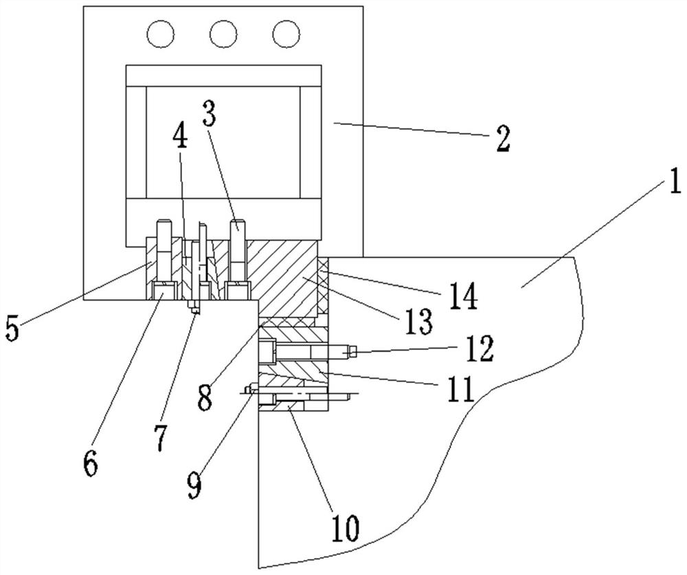
The invention discloses a guide rail adjusting device which is installed at the end corner of a sliding frame. The guide rail adjusting device comprises a base, a first adjusting block and a second adjusting block, and a sliding rail is further arranged at the end corner of the sliding frame; the base is arranged at the outer end of the sliding rail and detachably connected with the sliding rail, and the first adjusting block is detachably connected with the base; the second adjusting block comprises a second wedge-shaped piece; and a first guide rail plate is fixedly connected between the contact faces of the sliding rail and the sliding frame, the sliding rail is fixedly connected with the second wedge-shaped piece through a matching block, the matching block is connected with the sliding frame through a second fastening bolt, and a second guide rail plate is fixedly connected between the contact faces of the sliding rail and the matching block. By arranging the wedge-shaped piece, the sliding frame and the sliding rail can be kept in full and tight contact by adjusting the wedge-shaped piece, then the sliding accuracy of the sliding frame is improved, the product quality is guaranteed, and meanwhile the service life of the sliding frame is prolonged.

Description

technical field [0001] The invention relates to the field of guide rail adjustment, in particular to a guide rail adjustment device. Background technique [0002] For the pressing of the die, it is often necessary to use the carriage to drive the die to press down. Most of the existing carriages use cylindrical carriages, which are similar to oil cylinders. However, after long-term use, the carriages will wear out, resulting in slippage. There is a gap between the frames, and then the die will shift when sliding, and the accuracy of the up and down movement cannot be guaranteed, resulting in the failure of product quality. Contents of the invention [0003] In order to overcome the above disadvantages, the present invention provides a guide rail adjusting device. [0004] A guide rail adjustment device installed at the end corner of a carriage; it includes a base, a first adjustment block and a second adjustment block, and a slide rail is provided at the end corner of the...

Claims


Application Information

Patent Timeline
Patent Type & Authority Applications(China)
IPC IPC(8): F16C29/12F16C29/02
CPCF16C29/02F16C29/126
Inventor 张辕李源李杨李宝莹成超
Owner FUHUA ZHONGYUAN JIANGSU HEAVY MACHINERY TECH CO LTD
Learn More