High-water-head navigation power generation ship lock

A technology for high water head and ship locks, which is applied in the direction of ship locks, ship lifting devices, engine components, etc. It can solve the problems of high water head ship lock navigation and drainage waste, etc., and achieve the effects of saving navigation time, increasing speed, and reducing waste of water resources

Pending Publication Date: 2021-05-11
杨锡安
View PDF0 Cites 0 Cited by
  • Summary
  • Abstract
  • Description
  • Claims
  • Application Information

AI Technical Summary

Problems solved by technology

[0005] In view of the above situation, the object of the present invention is to provide a high-head navigable power generation ship lock, which adopts a combined structure in which irrigation, power generation and discharge corridors are arranged side by side on both sides of the upper and lower ends of the ship lock chamber, thereby overcoming the existing There is a huge waste of water in the navigation and discharge of high-head ship locks with high technology. Combined with the confluence corridor with a cross-shaped structure in the center of the bottom of the lock chamber, it can realize comprehensive utilization of water resources, and the navigation guarantee rate is high. Ship navigation is safe and reliable. The overall structure Scientific and reasonable, simple and compact, easy to install and operate, broad market prospects, easy to promote and use

Method used


Image

  • High-water-head navigation power generation ship lock
  • High-water-head navigation power generation ship lock

Examples


Embodiment 1

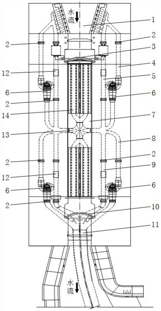
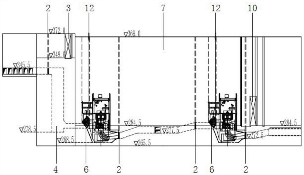
[0029] Embodiment 1: Reference figure 1 and figure 2 As shown, the present invention is suitable for the western region where my country's water conservancy resources are relatively abundant, and is generally preferably used for a maximum working water level of not less than 75m, a rated water level of 36m, and a lock length and width of 180m x 23m for navigable 1000-ton ships. The theoretical volume of water in the lock chamber that can be used for power generation is 180×23×70=289,800 m 3 According to the 17 times of ship navigation every day, the time for filling or releasing water in the lock chamber is 30 minutes each time, and the operation of the ship lock is calculated as 330 days a year. Four 41MW hydroelectric generators are selected, and the annual power generation is theoretically about 200 million degrees. ; When the sluice chamber is filled with water or discharged to generate electricity, the hydro-generator unit starts to start, and it takes about one minute t...


PUM


Abstract

The invention discloses a high-water-head navigation power generation ship lock. The ship lock comprises a ship lock chamber arranged between an upstream water inlet and a downstream water outlet, wherein an upper power generation gallery and an irrigation gallery are arranged on the two sides outside a lock wall at an upper end of the ship lock chamber respectively in parallel, a lower power generation corridor and a drainage corridor are arranged on two sides outside a lock wall at a lower end of the lock chamber of the ship lock in parallel, and water-turbine generator sets are arranged on the upper power generation corridor and the lower power generation corridor correspondingly; a converging gallery is arranged in the center of the bottom of the ship lock chamber and communicates with the upper power generation gallery, the irrigation gallery, the lower power generation gallery, the drainage gallery and the ship lock chamber; the structure that the irrigation galleries, the power generation galleries and the drainage galleries are arranged outside the lock walls at an upper end and a lower end of the ship lock in parallel is adopted, so the defect that huge waste exists in navigation drainage of a high-water-head ship lock in the prior art is overcome, water resources can be comprehensively utilized by combining the converging galleries of a cross-shaped structure in the center of the bottom of the lock chamber, and navigation is safe and reliable; the ship lock is widely suitable for being matched with a water transport ship lock.

Description

technical field [0001] The invention relates to a waterway ship lock, in particular to a high-head navigable power generation ship lock. Background technique [0002] The ship lock is the most widely used waterway navigation structure. It controls the water level of the lock chamber by opening and closing the filling and discharging sluice gate, and realizes the step-like lifting of the ship in the lock room, which can overcome the navigation difficulties caused by the water level drop of the channel; During the process, a large amount of water is directly discharged to the downstream through the ship lock water delivery corridor, resulting in the loss of energy stored in this part of the water body, especially for high head ship locks, which have high channel grades, large ship lock sizes, and large water level differences between upstream and downstream. The discharge of water downstream during the navigable operation of the ship lock will consume a large amount of water s...

Claims


Application Information

Patent Timeline
Patent Type & Authority Applications(China)
IPC IPC(8): E02C1/00E02C1/06E02C1/08F03B13/00
CPCE02C1/00E02C1/06E02C1/08F03B13/00F05B2220/706
Inventor 杨锡安段元振邹开明甘茂辉
Owner 杨锡安
Why Eureka
Try Eureka