Multi-axis machining center with automatic feeding and discharging functions

A technology of automatic loading and unloading, multi-axis processing, applied in stone processing equipment, stone processing tools, metal processing equipment and other directions, can solve the problem of inconvenient loading and unloading

Pending Publication Date: 2021-05-11
福建省嘉泰智能装备有限公司
View PDF0 Cites 3 Cited by
  • Summary
  • Abstract
  • Description
  • Claims
  • Application Information

AI Technical Summary

Problems solved by technology

[0002] With the development of science and technology, the product quality requirements for 3C sheets such as glass, ceramic sheets, glass-ceramic sheets, and sapphire are getting higher and higher, and because the thin and fragile structure of 3C sheets cannot withstand too much force, it is not only inconvenient to load and unload, Moreover, the existing clamps are also difficult to accurately and stably clamp and position the 3C sheet.

Method used


Image

  • Multi-axis machining center with automatic feeding and discharging functions
  • Multi-axis machining center with automatic feeding and discharging functions
  • Multi-axis machining center with automatic feeding and discharging functions

Examples


Embodiment 1

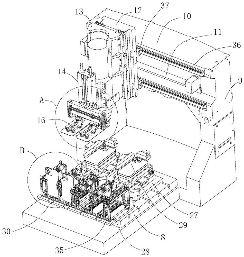
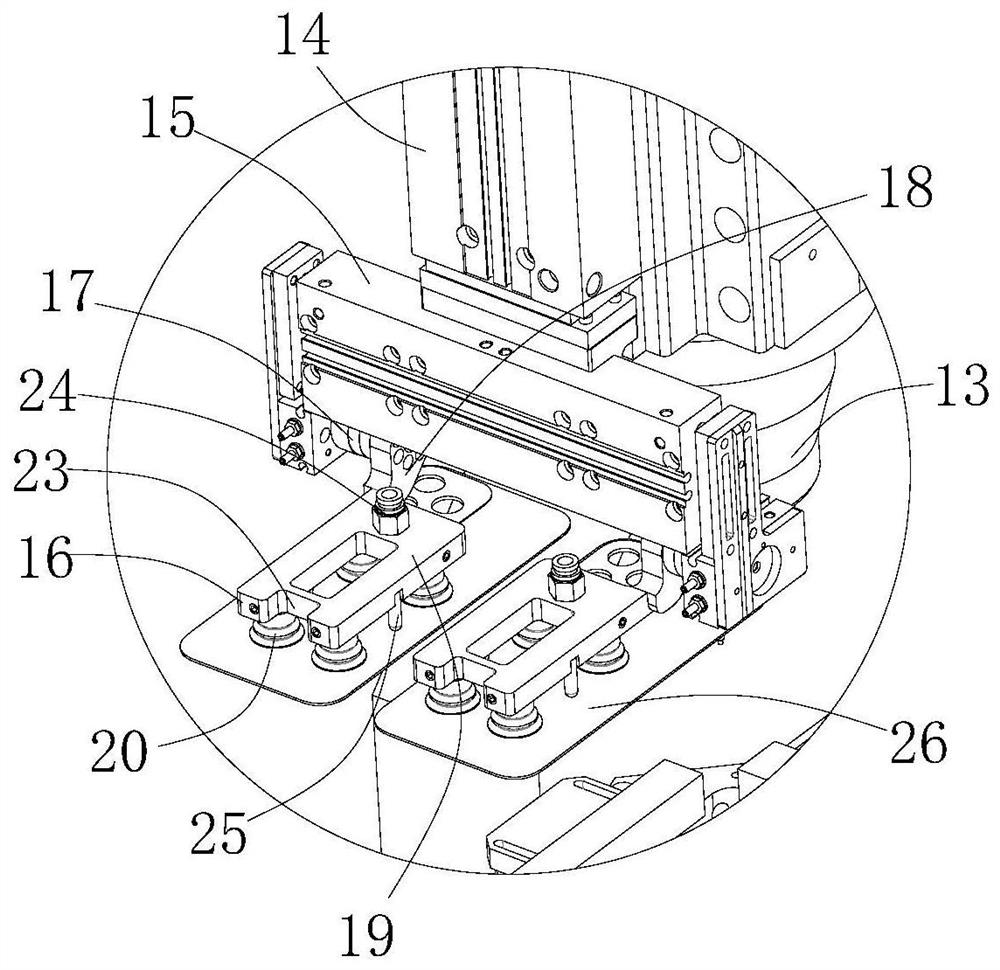
[0044] Such as Figure 1-6 As shown, a multi-axis machining center with automatic loading and unloading of the present invention includes a base 8, a gantry 9 in the X-axis direction is arranged above the base 8, a track in the Y-axis direction is provided below the base 8, and a The Y-axis traveling device that cooperates with the track, the gantry 9 includes a crossbeam 10 in the X-axis direction, and the front side of the crossbeam 10 is provided with an X-axis traveling device 11, and the X-axis traveling device 11 is provided with a first activity that moves along the X-axis direction. The part is connected with a Z-axis traveling device 12, and the second movable part that the Z-axis traveling device 12 is provided with moves along the Z-axis direction is connected with a machine head assembly 13, and the front side of the machine head assembly 13 is provided with a Z-axis drive cylinder 14, The movable end of the Z-axis drive cylinder 14 is provided with an X-axis drive...

Embodiment 2

[0049] Such as Figure 1-10 As shown, a multi-axis machining center with automatic loading and unloading of the present invention includes a base 8, a gantry 9 in the X-axis direction is arranged above the base 8, a track in the Y-axis direction is provided below the base 8, and a The Y-axis traveling device that cooperates with the track, the gantry 9 includes a crossbeam 10 in the X-axis direction, and the front side of the crossbeam 10 is provided with an X-axis traveling device 11, and the X-axis traveling device 11 is provided with a first activity that moves along the X-axis direction. The part is connected with a Z-axis traveling device 12, and the second movable part that the Z-axis traveling device 12 is provided with moves along the Z-axis direction is connected with a machine head assembly 13, and the front side of the machine head assembly 13 is provided with a Z-axis drive cylinder 14, The movable end of the Z-axis drive cylinder 14 is provided with an X-axis driv...


PUM


Abstract

The invention relates to the technical field of 3C sheet machining equipment, in particular to a multi-axis machining center with automatic feeding and discharging functions. The multi-axis machining center comprises a base, wherein a Y-axis walking device is arranged on the lower part of the base; an X-axis walking device is arranged above the base; a Z-axis walking device is arranged on the X-axis walking device; a machine head assembly is arranged on the Z-axis walking device; a Z-axis driving cylinder is arranged at the front side of the machine head assembly; an X-axis driving cylinder is arranged at the movable end of the Z-axis driving cylinder; the X-axis driving cylinder is provided with suction cup devices; the first suction cup device comprises a rotating device, an extending block, a hollow frame-shaped main body and four pneumatic suction cups; and a material frame is arranged at the front side of the base, and two inclined automatic clamps are arranged at the rear side of the base. By arranging the multi-axis drive double-station suction cup devices on the machining machine head, material machining and loading and unloading are integrated, the equipment structure is simplified, the cost is reduced, and the working efficiency is improved.

Description

technical field [0001] The invention relates to the technical field of 3C sheet processing equipment, in particular to a multi-axis machining center with automatic loading and unloading. Background technique [0002] With the development of science and technology, the product quality requirements for 3C sheets such as glass, ceramic sheets, glass-ceramic sheets, and sapphire are getting higher and higher, and because the thin and fragile structure of 3C sheets cannot withstand too much force, it is not only inconvenient to load and unload, Moreover, it is also difficult for the existing clamps to perform accurate and stable clamping and positioning of the 3C sheet. [0003] Therefore, it is necessary to provide a 3C sheet processing center in order to realize automatic loading and unloading and precise positioning of the fragile structure of the 3C sheet without causing damage, thereby facilitating more refined processing of the 3C sheet. Contents of the invention [0004...

Claims


Application Information

Patent Timeline
IPC IPC(8): B28D1/18B28D1/30B28D5/00B28D7/04B28D7/00B24B9/06B24B9/08B24B9/16B24B41/06B24B41/00
CPCB24B9/06B24B9/08B24B9/16B24B41/00B24B41/06B28D1/18B28D1/30B28D5/00B28D5/0094B28D7/00B28D7/046
Inventor 李敏之张彪
Owner 福建省嘉泰智能装备有限公司
Why Eureka
Try Eureka