Cutting device of a knurling machine
A cutting device and knurling machine technology, applied in the field of steel processing, can solve problems such as inability to meet production requirements, large noise, size differences, etc., and achieve the effects of improving stability, ensuring normal operation, and improving cutting accuracy
- Summary
- Abstract
- Description
- Claims
- Application Information
AI Technical Summary
Problems solved by technology
Method used
Image
Examples
Embodiment 1
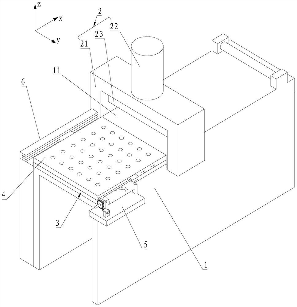
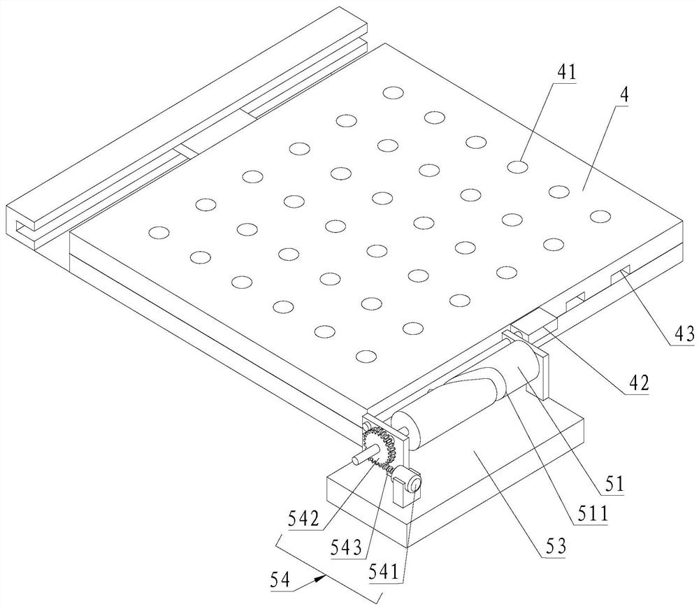
[0075] refer to Figure 1-Figure 3 , a cutting device for a knurl machine, comprising a workbench 1, a cutting mechanism 2, an adsorption mechanism 3, a discharge plate 4 and a discharge mechanism 5; the top of the workbench 1 has a cutting area 11; the cutting mechanism 2 is located above the cutting area 11 The adsorption mechanism 3 is embedded on the top of the workbench 1, and the adsorption mechanism 3 is located on the discharge side of the cutting area 11; the discharge plate 4 is slidably installed on the top of the adsorption mechanism 3 along the X-axis direction; the discharge mechanism 5 The output end is in transmission connection with the discharge plate 4, and the fixed end of the discharge mechanism 5 is installed on one side of the adsorption mechanism 3 in the Y-axis direction; the top of the adsorption mechanism 3 is provided with multiple rows of adsorption holes 31 parallel to each other along the Y-axis direction , the discharge plate 4 is provided with ...
Embodiment 2
[0084] The difference between this embodiment and the first embodiment lies in that the structure of the discharging mechanism 5 is different.
[0085] refer to figure 1 , image 3 and Figure 4 , the discharge mechanism 5 includes a circular cam 55, a second transmission rod 56, a second cam frame 57 and a second drive assembly; the second cam frame 57 is mounted on the top of the workbench 1; the circular cam 55 is mounted on the second The cam frame 57 is away from the side of the adsorption mechanism 3; the top of the circular cam 55 is provided with a second guide groove 511 in a quasi-rhombic shape; The output end of the output end passes through the top of the workbench 1 and is connected with the shaft center of the circular cam 55; the middle part of the second transmission rod 56 is rotatably installed on the side of the second cam frame 57 close to the adsorption mechanism 3; One end of the second transmission rod 56 is in transmission connection with the dischar...
PUM
 Abstract
Description
Claims
Application Information
 - R&D
- Intellectual Property
- Life Sciences
- Materials
- Tech Scout
- Unparalleled Data Quality
- Higher Quality Content
- 60% Fewer Hallucinations
Browse by: Latest US Patents, China's latest patents, Technical Efficacy Thesaurus, Application Domain, Technology Topic, Popular Technical Reports.
© 2025 PatSnap. All rights reserved.Legal|Privacy policy|Modern Slavery Act Transparency Statement|Sitemap|About US| Contact US: help@patsnap.com


