Eureka AIR delivers breakthrough ideas for toughest innovation challenges, trusted by R&D personnel around the world.

Overload protection device

A technology of overload protection and hub flange, which is applied in the direction of automatic clutches, clutches, mechanical equipment, etc., can solve problems such as pressure fluctuations, assembly accuracy deviations, large vibrations and noises, and achieve vibration and noise prevention and accurate working torque. Effect

Inactive Publication Date: 2009-10-21
TSUBAKI E&M +1
View PDF1 Cites 24 Cited by
  • Summary
  • Abstract
  • Description
  • Claims
  • Application Information

AI Technical Summary

Problems solved by technology

[0010] However, the problem with this existing overload protection device 500 is that the steel ball 520 is always in the state of being pushed by the spring 550 after the rotation transmission is cut off, so when the rotation is continuously input, every time the steel ball 520 and the hub flange When the V-shaped cavity 532 of 531 is aligned (at least one rotation occurs once), the steel ball 520 is accommodated in the V-shaped cavity 532 and the rotation is transmitted again. However, if the overload is not eliminated at this time, the rotation transmission will be cut off again as described above, resulting in a large Large vibration and noise, and accelerate the wear of the various components of the overload protection device and aggravate equipment loss
[0022] But the problem with this overload protection device is that the pushing force transmitted to the steel ball is transmitted from the spring through the pushing sleeve, holding ball and pushing plate, which will cause vibration and noise due to passing through many components
[0023] And because there are many components in the transmission path and there are many places where the force is dispersed, it will inevitably lead to fluctuations in the pushing force caused by deviations in strength, dimensional accuracy, assembly accuracy, and vibration, making it difficult to accurately set the overload protection device. working torque, and it is also easy to cause the action failure of the holding mechanism itself

Method used


Image

  • Overload protection device
  • Overload protection device
  • Overload protection device

Examples


Embodiment Construction

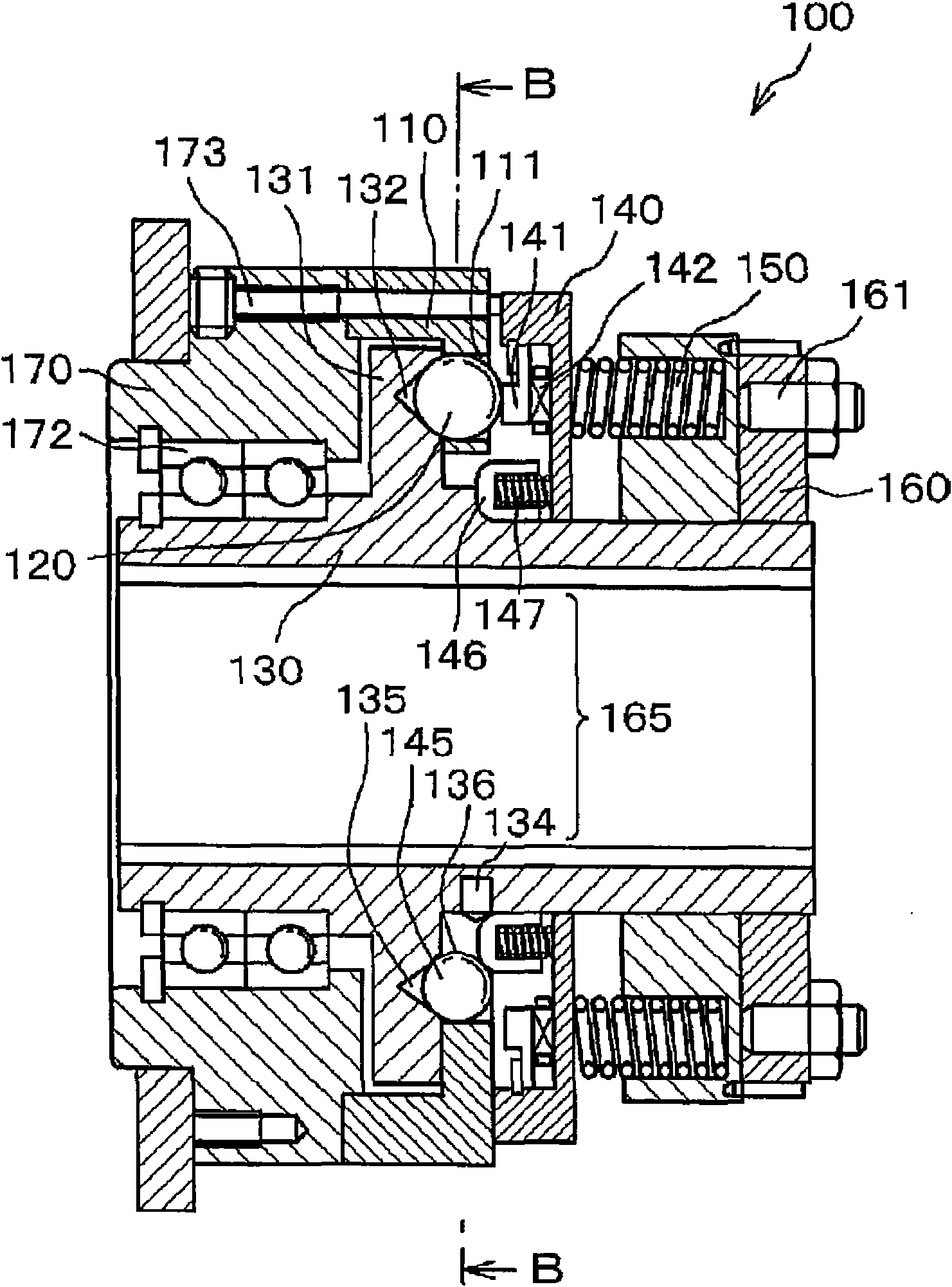
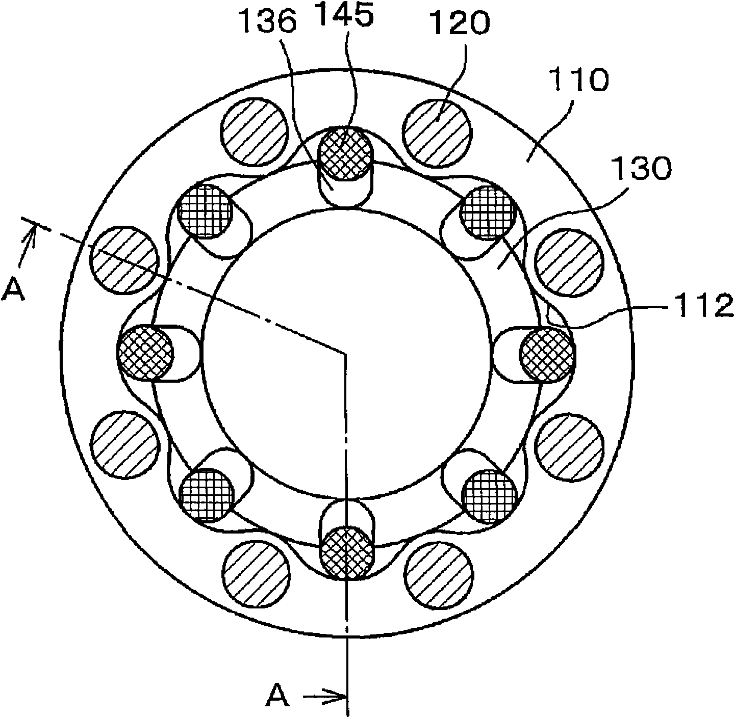
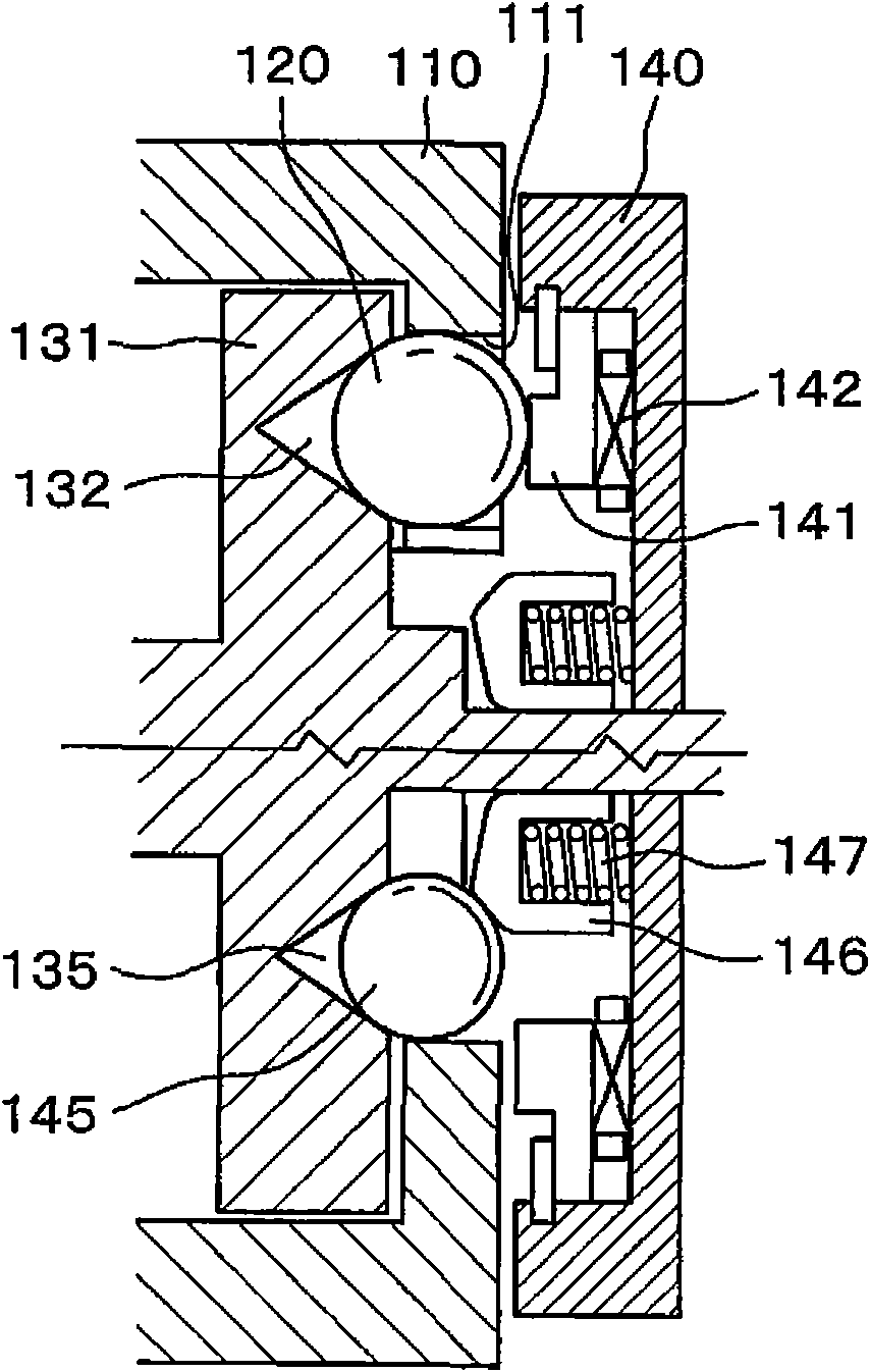
[0048] The overload protection device of the present invention has: a central flange holding a torque transmission element in a plurality of through holes provided in the direction of the rotation axis, disposed opposite to the central flange in the direction of the rotation axis, and having a function of engaging with the torque transmission element. The hub flange of the concave part of the hub flange, the pressing plate provided opposite to the central flange on the opposite side of the hub flange in the direction of the rotation axis and pressing the torque transmission element toward the direction of the hub flange, and the pressing plate when overloaded A holding mechanism for holding in a state of retreating against a pressing force, the above-mentioned holding mechanism includes: a stop ring provided on the side of the above-mentioned central flange of the above-mentioned pressing plate, and a holding ball arranged on the inner peripheral side of the above-mentioned cent...


PUM


Abstract

The invention provides a overload protection device, capable of keeping the rotary drive partition state and preventing from generating the vibration and noise because of the transference the path of the push pressure and accurately setting the operation torque and making a holding mechanism work reliably. the overload protection device has a central flange (110), a hub flange (131) and a push compressed plate for pushing a steel ball (120) to rotate and drive, wherein a holding mechanism (165) for keeping the partition in the over loading comprises a retaining ring (146) mounted at the central flange side of the push pressure plate (140) and a holding ball (145) arranged at the internal circumstance side of the central flange (110).

Description

technical field [0001] The present invention relates to an overload protection device for isolating rotation transmission when an overload occurs in a torque transmission mechanism. Background technique [0002] In the past, as an overload protection device that interrupts the rotation transmission when an overload occurs in the torque transmission mechanism, there are a central flange that holds the torque transmission element in a plurality of through holes provided in the direction of the rotation axis, and the central flange. A hub flange disposed axially opposite and having a concave portion engaged with the above-mentioned torque transmission element is disposed opposite to the above-mentioned central flange on a side opposite to the axial direction of the hub flange and directs the above-mentioned torque transmission element toward the above-mentioned A push plate that pushes in the direction of the hub flange. [0003] These overload protection devices 500, such as ...

Claims


Application Information

Patent Timeline
IPC IPC(8): F16D43/20F16D43/206
CPCF16D43/206
Inventor 梅田真一松本正博
Owner TSUBAKI E&M
Why Eureka
Eureka Blog
Learn More