Metal pipe bending machine

A metal pipe and bending machine technology, which is applied in metal processing equipment, forming tools, feeding devices, etc., can solve the problems of reducing user production efficiency, affecting the accuracy of metal pipes, and consuming time and effort.

Active Publication Date: 2021-05-11
江苏众信绿色管业科技有限公司
View PDF7 Cites 3 Cited by
  • Summary
  • Abstract
  • Description
  • Claims
  • Application Information

AI Technical Summary

Problems solved by technology

[0003] In the process of realizing the present invention, it is found that at least the following problems in the prior art have not been resolved: 1. Some traditional bending machines need to bend different diameters The pipe needs to replace the mold of the bending mechanism, which is not convenient for the user to operate, takes time and effort, and reduces the production efficiency of the user;
[0004]2. When bending some metal pipes with rust stains on the surface, a large amount of rust stains will fall off the work surface, and the accumulation of rust stains will often lead to bending The angular offset of the mechanism, thereby reducing the efficiency of the use of the device
[0005]3. When it is necessary to bend a metal pipe with a thinner wall thickness and a larger inner diameter, when the metal pipe with a thinner wall thickness and a larger inner diameter is subjected to When the force is uneven, the metal tube will be flattened and protruded into the cavity of the metal tube, thus affecting the precision of the metal tube itself

Method used


Image

  • Metal pipe bending machine
  • Metal pipe bending machine
  • Metal pipe bending machine

Examples


Embodiment Construction

[0037] The technical solutions of the present invention will be clearly and completely described below in conjunction with the embodiments. Obviously, the described embodiments are part of the embodiments of the present invention, but not all of them. Based on the embodiments of the present invention, all other embodiments obtained by persons of ordinary skill in the art without making creative efforts belong to the protection scope of the present invention.

[0038] In describing the present invention, it is to be understood that the terms "center", "longitudinal", "transverse", "length", "width", "thickness", "upper", "lower", "front", " Back", "Left", "Right", "Vertical", "Horizontal", "Top", "Bottom", "Inner", "Outer", "Clockwise", "Counterclockwise", etc. or The positional relationship is based on the orientation or positional relationship shown in the drawings, which is only for the convenience of describing the present invention and simplifying the description, rather t...


PUM


Abstract

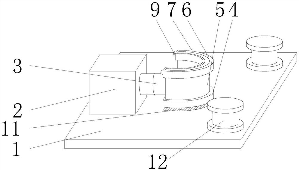
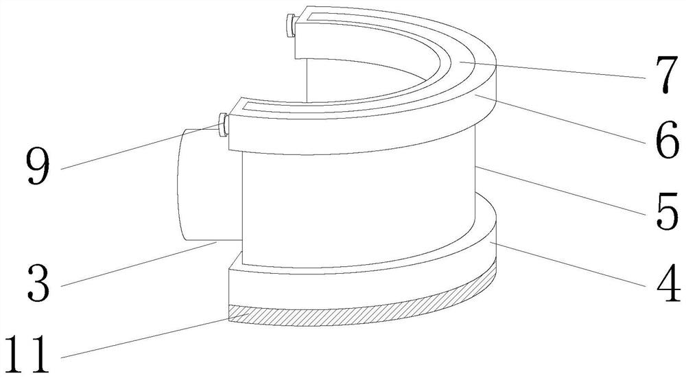
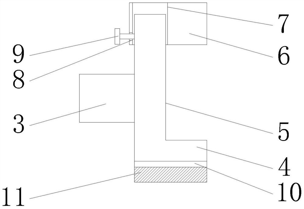
The invention provides a metal pipe bending machine. The metal pipe bending machine comprises a supporting plate, wherein an air cylinder is fixedly connected to the position, close to one side, of the outer surface of the upper end of the supporting plate; a sleeve is movably connected to the outer surface of the other side of the air cylinder, and a baffle plate is fixedly connected to the outer surface of the other side of the sleeve; a first abutting ring is fixedly connected to the outer surface of the lower end of the baffle plate, and a second abutting ring is arranged on the outer surface of the upper end of the baffle plate; an abutting column is arranged in the position, far away from one side, of the outer surface of the upper end of the supporting plate; the first abutting ring and the baffle plate are both of an arc-shaped structure and form an integral structure; and the diameter of the first abutting ring is greater than that of the baffle plate. The metal pipe bending machine has the advantages that a user can conveniently adjust the position of the second abutting ring according to the diameters of different clamped pipes; the surface of the supporting plate can be scraped through a cleaning brush when the pipes with rust stains are bent, and the probability that the bending angle of the pipes deviates due to accumulation of the rust stains is reduced; and the use efficiency of the device is improved.

Description

technical field [0001] The invention relates to the technical field of pipe bending machines, in particular to a metal pipe bending machine. Background technique [0002] The bending machine is a machine capable of bending thin plates. Its structure mainly includes a bracket, a workbench and a clamping plate. The workbench is placed on the bracket. The workbench is composed of a base and a pressure plate. Connected, the base is composed of a seat shell, a coil and a cover plate. The coil is placed in the depression of the seat shell, and the top of the depression is covered with a cover plate. When in use, the coil is energized by a wire. Clamping of thin plates between. Due to the use of electromagnetic force clamping, the pressure plate can be made into a variety of workpiece requirements, and the workpiece with side walls can be processed, and the operation is also very simple. [0003] In the process of realizing the present invention, it is found that at least the fol...

Claims


Application Information

Patent Timeline
Patent Type & Authority Applications(China)
IPC IPC(8): B21D7/06B21D37/04B21D43/00B08B1/00
CPCB21D7/06B21D37/04B21D43/003B08B1/002B08B1/008
Inventor 王硕孔玉
Owner 江苏众信绿色管业科技有限公司
Why Eureka
Try Eureka