Moving bed reactor and use method thereof

A moving bed reactor and reactor technology, applied in chemical instruments and methods, chemical/physical processes, etc., can solve problems such as large equipment investment, low reactor space utilization, and complex operation.

Pending Publication Date: 2021-05-11
ATHCO ENG SHANGHAI CO LTD
View PDF8 Cites 2 Cited by
  • Summary
  • Abstract
  • Description
  • Claims
  • Application Information

AI Technical Summary

Problems solved by technology

[0005] Finally, the heat transfer performance of the cross-flow moving bed has been criticized. In order to solve this problem, most moving bed reactors adopt the method of multi-stage series and inter-stage heat exchange (CN102875469A) or the method of external heat exchange of the reactor (CN105218304B) For heat removal, the above two methods will lead to low space utilization of the reactor, large equipment investment and complicated operation

Method used


Image

  • Moving bed reactor and use method thereof
  • Moving bed reactor and use method thereof
  • Moving bed reactor and use method thereof

Examples


Embodiment 1

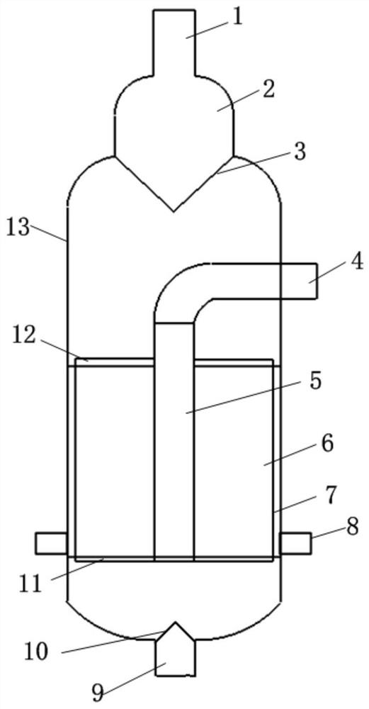
[0035] A moving bed reactor, with reference to figure 1 , the reactor comprises a reactor shell 13, the reactor shell 13 is provided with a catalyst loading area, the upper end of the reactor shell 13 is provided with a catalyst feed port 1, and its lower end is provided with a catalyst discharge port 9, where the catalyst feed The feed port 1 is provided with a metering buffer tank 2 and a cone valve 3 at the feed port. The catalyst discharge port 9 is provided with a discharge port cone valve 10 . The moving bed reactor is a radial reactor, and the reactor shell 13 is cylindrical.

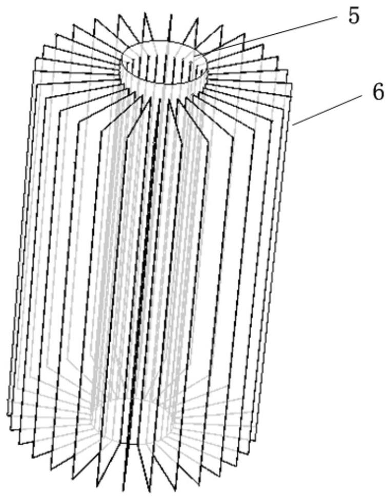
[0036] Such as figure 2 , 3, a plurality of plate pairs and the gas-phase center tube form a structure in which the raw material flows radially, and the plate channel is the catalyst loading area and the raw material reaction area, which also has the function of heat exchange. The catalyst loading area includes a gas phase center tube 5, a plurality of plates surrounding the outside of the g...

Embodiment 2

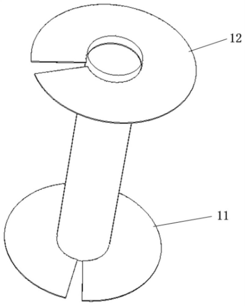
[0038] Taking the xylene isomerization reaction as an example to further illustrate the present invention, the mixed gas of raw material liquid, high-temperature solvent and carrier gas enters the gas phase central tube 5 from the gas phase central tube inlet 4, and then distributes to each plate channel 6 to contact with the catalyst After the reaction occurs, the product enters the gas annulus 7, and then is discharged from the gas phase outlet 8 to be separated and refined downstream to obtain xylene isomerization products. If the catalyst activity cannot meet the reaction requirements, first put the regenerated or fresh catalyst into the metering buffer tank 2, open the cone valve 3 of the feed inlet and the cone valve 10 of the discharge outlet, the active life of the reaction catalyst is longer, and the intermittent Type loading and unloading, turn the gap and rotate the feeding tray 12 to the vacancy, and follow the rotation direction to the gap to rotate the discharge t...


PUM


Abstract

The invention relates to a moving bed reactor and a use method thereof. The reactor comprises a reactor shell, a catalyst filling area is arranged in the reactor shell, a catalyst feeding port is formed in the upper end of the reactor shell, and a catalyst discharging port is formed in the lower end of the reactor shell; the catalyst filling area comprises a gas-phase central pipe, a plurality of plates arranged outside the gas-phase central pipe in a surrounding manner, a rotatable gap rotary feeding disc arranged at the upper end of the gas-phase central pipe and a rotatable gap rotary discharging disc arranged at the lower end of the gas-phase central pipe, and the plates are arranged in parallel at equal intervals along the axial direction (circumferential direction) of the outer pipe wall of the gas-phase central pipe; and a plate-type channel is formed between every two adjacent plates, and the gap rotary feeding disc and the gap rotary discharging disc are provided with notches consistent with the section shapes of the plate-type channels. The reactor can intermittently and continuously load and unload a catalyst, ensures the loading and unloading uniformity of the catalyst, and effectively avoids the problem of non-uniform axial distribution of airflow.

Description

technical field [0001] The invention belongs to the field of chemical equipment, and in particular relates to a moving bed reactor and a using method thereof. Background technique [0002] The moving bed reactor is a reactor form used to realize fluid-solid phase contact. The solid material gradually moves down in the reactor to the bottom and is discharged by gravity, and the fluid reacts with the solid phase material. The moving bed reactor has the characteristics of both the fixed bed reactor and the fluidized bed reactor, and is especially suitable for reactions where the catalyst deactivation rate is moderate, but cyclic regeneration is still required. The operating performance and catalyst requirements of the moving bed reactor are between the fixed bed and the fluidized bed. Compared with the fixed bed, the moving bed reactor has the characteristics of small pressure drop and low investment; compared with the entrained bed, The moving bed reactor has the advantages o...

Claims


Application Information

Patent Timeline
IPC IPC(8): B01J8/12
CPCB01J8/12B01J8/0015
Inventor 傅建敏余圣婴倪昊尹方晨辰
Owner ATHCO ENG SHANGHAI CO LTD
Why Eureka
Try Eureka