
Dielectric waveguide filter

A dielectric waveguide and filter technology, which is applied in the field of dielectric waveguide filters, can solve problems such as the fracture of the isolation channel and reduce the overall structural strength of the dielectric waveguide filter, so as to improve the use effect, strong integrity, and improve the overall structural strength. Effect

Inactive Publication Date: 2021-05-07
宜宾红星电子有限公司
View PDF5 Cites 0 Cited by
  • Summary
  • Abstract
  • Description
  • Claims
  • Application Information

AI Technical Summary

Problems solved by technology

Due to the small size of the existing dielectric waveguide filter, the interval between the two input-output coupling blind holes is small, and an isolation structure needs to be set between the two input-output coupling blind holes. The isolation structure currently used is an isolation Slots and isolation slots have a good isolation effect, but the isolation slots reduce the overall structural strength of the dielectric waveguide filter, and the shortest distance between the isolation slot and the edge of the ceramic body is less than 1.6m, making the dielectric waveguide filter dry-pressed Or when external force is applied during debugging, it is easy to break at the isolation channel, which affects its use

Method used


Image

  • Dielectric waveguide filter
  • Dielectric waveguide filter
  • Dielectric waveguide filter

Examples


Embodiment Construction

[0017] The present invention will be further described below in conjunction with the accompanying drawings and specific embodiments.

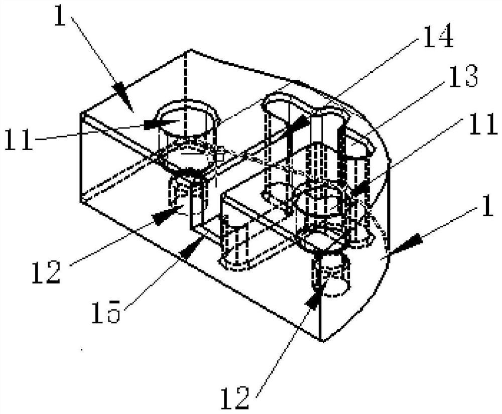
[0018] Such as figure 1 As shown, the dielectric waveguide filter of the present invention includes a ceramic body, and the ceramic body includes a window surface and a feeding blind hole surface oppositely arranged, that is, the window surface is the top surface of the ceramic body, and the feeding blind hole surface is a ceramic body The bottom surface of the ceramic body includes two dielectric waveguide feeding cavities 1, and the dielectric waveguide feeding cavity 1 is provided with a tuning blind hole 11 and an input-output coupling blind hole 12, and the opening of the tuning blind hole 11 is located on the window surface, and the input The orifice of the output coupling blind hole 12 is located on the feeding blind hole surface, and an isolation structure is arranged between the two input and output coupling blind holes 12. The isolati...


PUM

PropertyMeasurementUnit
depthaaaaaaaaaa

Abstract

The invention relates to the technical field of filters, and in particular relates to a dielectric waveguide filter which comprises a ceramic body, the ceramic body comprises two dielectric waveguide feed cavities, each dielectric waveguide feed cavity is provided with a tuning blind hole and an input and output coupling blind hole, an orifice of each input and output coupling blind hole is located on a feed blind hole surface, an isolation structure is arranged between the two input and output coupling blind holes, the isolation structure comprises a first isolation through hole, a second isolation through hole and an isolation blind hole, one end of the second isolation through hole is connected with the first isolation through hole, and the other end of the second isolation through hole is connected with the isolation blind hole. The isolation structure has a good isolation effect, compared with an isolation through groove or an isolation through hole in the prior art, the dielectric waveguide filter is higher in integrity through the arrangement of the isolation blind holes, the shortest distance between the second isolation through hole and the edge of the ceramic body is larger than 2 mm, and therefore the overall structural strength of the dielectric waveguide filter is effectively improved.

Description

technical field [0001] The invention relates to the technical field of filters, in particular to dielectric waveguide filters. Background technique [0002] Since the dielectric waveguide filter has the advantages of small size, light weight, and excellent performance, it is more suitable for the use of 5G base stations. Due to the small size of the existing dielectric waveguide filter, the interval between the two input-output coupling blind holes is small, and an isolation structure needs to be set between the two input-output coupling blind holes. The isolation structure currently used is an isolation Slots and isolation slots have a good isolation effect, but the isolation slots reduce the overall structural strength of the dielectric waveguide filter, and the shortest distance between the isolation slot and the edge of the ceramic body is less than 1.6m, making the dielectric waveguide filter dry-pressed Or when an external force is applied during debugging, it is easy...

Claims


Application Information

Patent Timeline
Patent Type & Authority Applications(China)
IPC IPC(8): H01P1/212
CPCH01P1/212
Inventor 段冰尚华蔡文新官国武
Owner 宜宾红星电子有限公司
Learn More