
Expansion machine nozzle regulating device and expansion machine

A nozzle adjustment and expander technology, applied in the field of expanders, can solve the problems of gear design, processing and manufacturing capacity constraints, cost increase, and the inability to apply a front-type nozzle adjustment mechanism.

Pending Publication Date: 2021-05-07
SHENYANG BLOWER WORKS GROUP CORP
View PDF4 Cites 0 Cited by
  • Summary
  • Abstract
  • Description
  • Claims
  • Application Information

AI Technical Summary

Problems solved by technology

However, with the continuous increase of the production capacity demand of the PTA device, the scale of the centripetal expander is also becoming larger and larger, which requires that the center distance of the gearbox must be increased to meet the needs of the structural design. For the expander using the outer volute This problem is more prominent
As we all know, the increase of the center distance will not only lead to a sharp increase in cost, but more importantly, the design and manufacturing capabilities of gears will be restricted.
[0004] The form of the inner volute can effectively reduce the center distance of the gearbox, reduce the radial size of the unit, and has little impact on the performance of the expander. It is an inevitable trend to realize the design of large-scale centripetal expanders. However, due to the Due to structural limitations, the front-end nozzle adjustment mechanism cannot be applied

Method used


Image

  • Expansion machine nozzle regulating device and expansion machine
  • Expansion machine nozzle regulating device and expansion machine
  • Expansion machine nozzle regulating device and expansion machine

Examples


Embodiment Construction

[0038] In describing the present invention, it should be understood that the terms "center", "longitudinal", "transverse", "length", "width", "thickness", "upper", "lower", "front", " Orientation or position indicated by "back", "left", "right", "vertical", "horizontal", "top", "bottom", "inner", "outer", "clockwise", "counterclockwise", etc. The relationship is based on the orientation or positional relationship shown in the drawings, and is only for the convenience of describing the present invention and simplifying the description, rather than indicating or implying that the referred device or element must have a specific orientation, be constructed and operated in a specific orientation, therefore It should not be construed as a limitation of the present invention.

[0039] In addition, the terms "first" and "second" are used for descriptive purposes only, and cannot be interpreted as indicating or implying relative importance or implicitly specifying the quantity of indic...


PUM


Abstract

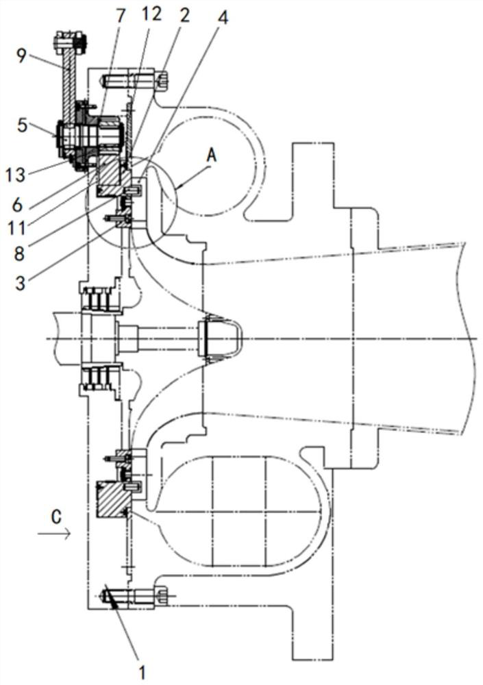
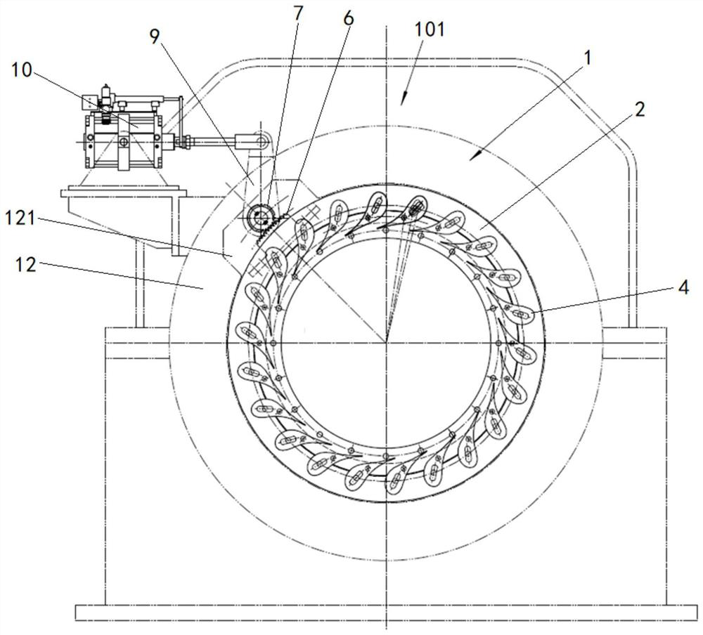
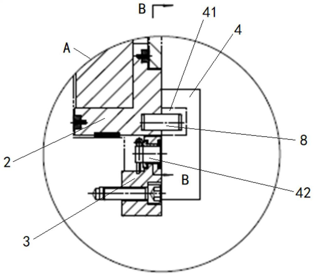
The invention discloses an expansion machine nozzle regulating device and an expansion machine, relates to the technical field of expansion machines, and mainly aims to provide a rear-mounted nozzle regulating device so that the expansion machine can adopt an inner volute form. According to the main technical scheme, the expansion machine nozzle regulating device comprises an end flange, a ring body, a plurality of nozzle blades and a transmission mechanism, wherein the end flange is provided with a gear box side used for being connected with a gear box of the expansion machine; the ring body comprises a rotating ring rotationally arranged on the end flange and a fixed ring fixedly arranged on the end flange and located in the rotating ring; the nozzle blades are arranged in the circumferential direction of the rotating ring, and the two ends of the nozzle blades are rotationally connected to the fixed ring and the rotating ring correspondingly; the transmission mechanism comprises a driving shaft, a transmission part and a gear; the transmission part is connected to the rotating ring, and meshing teeth are arranged on the transmission part; the gear is rotatably arranged on the end flange and is in meshed connection with the transmission part; and the driving shaft is rotatably arranged on the end flange, one end of the driving shaft penetrates to the gear side, and the other end of the driving shaft is connected with the gear.

Description

technical field [0001] The invention relates to the technical field of expanders, in particular to an expander nozzle adjustment device and an expander. Background technique [0002] In recent years, with the increasingly serious energy crisis, the enhancement of environmental protection awareness, and the increase of the scale of chemical equipment, the market demand for expanders that use the waste heat and pressure of chemical tail gas for energy recovery is also increasing. [0003] Taking the PTA (purified terephthalic acid) plant in the chemical industry as an example, the tail gas energy recovery turbine usually adopts a two-stage gear assembled centripetal expander, and in order to adapt to the adjustment of variable working conditions, the operating efficiency of the expander under variable working conditions is improved. Economical, usually with a nozzle adjustment mechanism. For small and medium-sized PTA plants, the assembled centripetal expander usually adopts ...

Claims


Application Information

Patent Timeline
Patent Type & Authority Applications(China)
IPC IPC(8): F01D17/16
CPCF01D17/165
Inventor 裴威郑志国罗劲艾宏伟于小丹么立新辛海涛
Owner SHENYANG BLOWER WORKS GROUP CORP
Learn More