Power line and resistance wire plugging machine of light-emitting device

A technology for light-emitting devices and power cords, applied in metal processing, metal processing equipment, manufacturing tools, etc., can solve the problems of difficult to guarantee assembly quality, easy to miss insertion, wrong insertion, unfavorable promotion and application, etc., to ensure assembly quality, reduce The effect of missing insertion and automatic and flexible switching

Pending Publication Date: 2021-05-07
苏州迅益科系统科技有限公司
View PDF0 Cites 0 Cited by
  • Summary
  • Abstract
  • Description
  • Claims
  • Application Information

AI Technical Summary

Problems solved by technology

[0002] The light-emitting device includes a housing and a substrate. The substrate is press-fitted on the bottom of the housing, and fixed resistance wires and power lines are respectively inserted into the mounting holes on the substrate. On the conveyor line, one station is manually inserted with resistance wires, and the other station is manually inserted with power lines. After the resistance wires and power lines are inserted, the substrate is sent to the next process for bending and assembly, which requires a lot of labor. In addition, the wire insertion process is to operate the substrate one by one, which is inefficient. After long-term manual work fatigue, it is easy to miss or mis-insert, and the assembly quality is difficult to guarantee.
[0003] In addition, since the substrate size, full-page size, arrangement, substrate center distance and other parameters corresponding to products of different specifications may be different, and the length of resistance wire or power cord may also vary, and the existing plug-in machine can only be used for The substrate of a product with a specific specification and the wire body of a specific length lead to the need to prepare multiple plug-in machines when the product is changed, which has poor versatility and is not conducive to popularization and application.

Method used


Image

  • Power line and resistance wire plugging machine of light-emitting device
  • Power line and resistance wire plugging machine of light-emitting device
  • Power line and resistance wire plugging machine of light-emitting device

Examples


Embodiment Construction

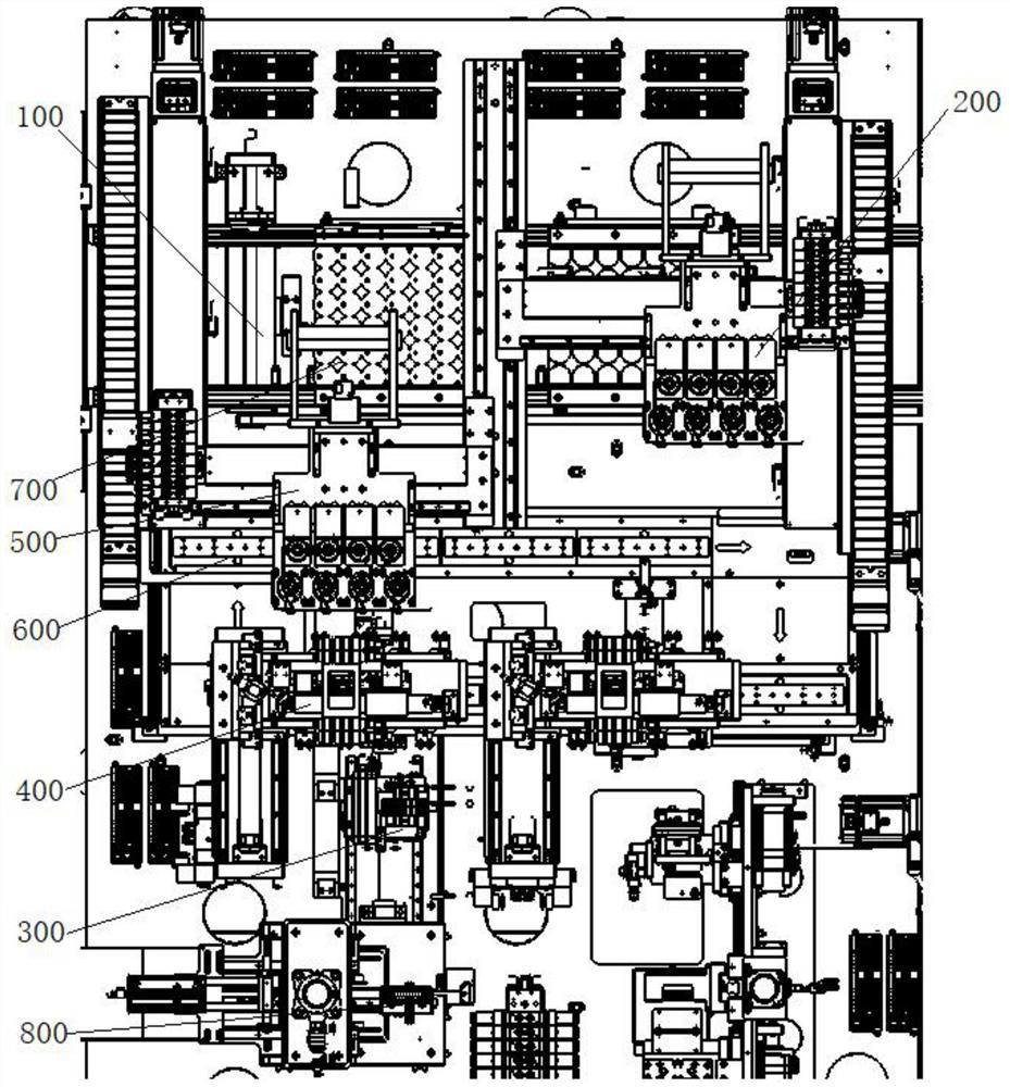
[0048] like figure 1 As shown, a power cord and resistance wire insertion machine for a light-emitting device, which installs a resistance wire insertion module 100 and a power cord insertion module 200 side by side along the X-axis direction on a frame, and the resistance wire insertion module 100 and The power cord insertion modules 200 each include a retrieving mechanism 300 , a clamping mechanism 400 and a wire insertion mechanism 500 , and the buffer mechanism 600 and the substrate conveying line 700 are both cyclically moved between the resistance wire insertion module 100 and the power cord insertion module 200 .

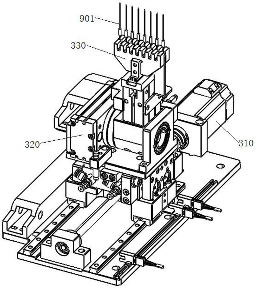
[0049] like figure 2 As shown, the retrieving mechanism 300 is used to remove a row of horizontally placed parts (resistance wires or power cords) from the waiting station 800 and convert them into a first posture, which forms an angle with the horizontal plane, Preferably, the first posture is perpendicular to the horizontal plane, so that the next proces...


PUM


Abstract

The invention provides a power line and resistance wire plugging machine of a light-emitting device. The power line and resistance wire plugging machine comprises a material taking mechanism, a caching mechanism, a material clamping mechanism and a wire inserting mechanism, the material taking mechanism is used for taking away a row of parts which are horizontally placed from a material waiting station and converting the parts into a first posture, and an included angle is formed between the first posture and the horizontal plane; the caching mechanism is used for caching the parts and comprises a plurality of carriers for temporarily storing the parts and a first driving assembly for driving the carriers to circularly move in the horizontal plane; the material clamping mechanism is used for clamping the parts to the carriers from the material taking mechanism, and the material clamping mechanism comprises a YZ-axis driving piece, a variable-pitch module installed on the YZ-axis driving piece and a plurality of second pneumatic fingers installed on the variable-pitch module; and the wire inserting mechanism is used for inserting the parts on the caching mechanism into the substrate of a substrate conveying line. According to the power line and resistance wire plugging machine, the labor amount of assembly is reduced, the working efficiency is high, the universality is strong, the phenomena of missing insertion, misplug and the like are avoided, and the assembly quality is ensured.

Description

technical field [0001] The invention belongs to the technical field of electronic device assembly, and in particular relates to a power cord and resistance wire insertion machine for a light-emitting device. Background technique [0002] The light-emitting device includes a housing and a substrate. The substrate is press-fitted on the bottom of the housing, and fixed resistance wires and power lines are respectively inserted into the mounting holes on the substrate. On the conveyor line, one station is manually inserted with resistance wires, and the other station is manually inserted with power lines. After the resistance wires and power lines are inserted, the substrate is sent to the next process for bending and assembly, which requires a lot of labor. In addition, the wire insertion process is to work on the substrate one by one, which is inefficient. After long-term manual work fatigue, it is easy to miss or mis-insert the phenomenon, and the assembly quality is difficu...

Claims


Application Information

Patent Timeline
Patent Type & Authority Applications(China)
IPC IPC(8): B23P19/00
CPCB23P19/00B23P19/007
Inventor 汪鹏李昂主中飞郑俊杰
Owner 苏州迅益科系统科技有限公司
Why Eureka
Try Eureka