A small-pitch view area guided three-dimensional display system and method
A three-dimensional display and guidance technology, applied in the direction of instruments, to achieve the effect of improving three-dimensional visual comfort and overcoming focus-convergence conflicts
- Summary
- Abstract
- Description
- Claims
- Application Information
AI Technical Summary
Problems solved by technology
Method used
Image

Examples
Embodiment 1
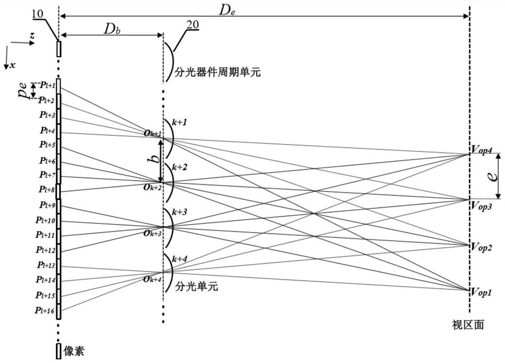
[0065] like image 3 , taking the cylindrical lens grating and the generation of 4 initial viewing areas as an example, along the transmission direction of the outgoing light from the pixels of the display screen 10, the spectroscopic device 20 is placed in front of the display screen 10, and based on the principle of light splitting, the initial viewing area V is generated op1 , V op2 , V op3 , and V op4 . When only the display screen 10 and the light splitting device 20 exist, the pixel P of the display screen 10 l+1 , P l+5 , P l+9 , P l+13 , ... constitute a pixel group in the initial view area V op1 Visible inside, pixel P l+2 , P l+6 , P l+10 , P l+14 , ... constitute a pixel group in the initial view area V op2 Visible inside, pixel P l+3 , P l+7 , P l+11 , P l+15 , ... constitute a pixel group in the initial view area V op3 Visible inside, pixel P l+4 , P l+8 , P l+12 , P l+16 , ... constitute a pixel group in the initial view area V op4 Visible i...
Embodiment 2
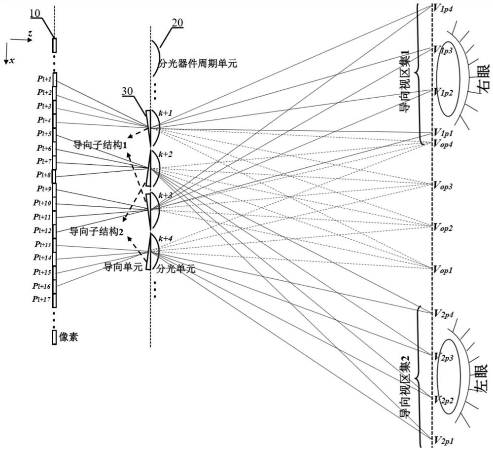
[0070]Using the timing controllable optical splitting device 20 and / or the timing controllable guiding device 30, at M adjacent time points at intervals of Δt / M, M groups of different optical splitting unit 20 and guiding unit 30 pairs appear in sequence. The guiding device 30 at each time point is composed of L groups of guiding substructures, and the guiding units of the guiding device 30 and the light-splitting devices of the light-splitting device 20 correspond one-to-one to form a light-splitting unit-guide unit pair. Then, more L×M guide viewport sets can be formed within the time Δt by means of time division multiplexing. like Figure 5 , taking L=2 and M=2 as an example. At the time point T within the time period T~T+Δt, similar to the process described in Embodiment 1, through L=2 guide substructures, two guide viewport sets are generated, the guide viewport set 1 and the guide viewport set 2. Then, at the time point T+Δt / 2 within the time period T˜T+Δt, the optica...
Embodiment 3
[0078] In the above system, a switching device 40 composed of N groups of controllable switching apertures can be further introduced. Similarly, along the transmission direction of the light emitted from the pixels of the display screen 10 , the light splitting device 20 is placed in front of the display screen 10 . The guiding device 30 and the switching device 40 are introduced. The guiding unit of the guiding device 30 and the respective constituent apertures of the switching device 30 are in real-time one-to-one correspondence with the light-splitting units of the light-splitting device 20. The unit and the guide unit form a beam splitting unit-guide unit pair. Each constituent aperture of the switching device 40 is divided into N groups, and within a time period of Δt, one of the N groups of apertures of the switching device 40 is turned on, and the beam splitting unit-guide unit pair corresponding to this group of apertures one-to-one is gated. Specifically, within the ...
PUM
 Abstract
Description
Claims
Application Information
 - R&D
- Intellectual Property
- Life Sciences
- Materials
- Tech Scout
- Unparalleled Data Quality
- Higher Quality Content
- 60% Fewer Hallucinations
Browse by: Latest US Patents, China's latest patents, Technical Efficacy Thesaurus, Application Domain, Technology Topic, Popular Technical Reports.
© 2025 PatSnap. All rights reserved.Legal|Privacy policy|Modern Slavery Act Transparency Statement|Sitemap|About US| Contact US: help@patsnap.com