Tubular muffler for automobile

A muffler and tube type technology, applied in muffler devices, machines/engines, engine components, etc., can solve problems such as non-targeted noise elimination, sound wave weakening muffling effect, inability to eliminate noise, etc., to prevent water or impurities from entering The effect of pipeline and noise elimination is remarkable, and the effect of convenient maintenance

Inactive Publication Date: 2021-05-04
DONGFENG AUTOMOBILE COMPANY
View PDF8 Cites 0 Cited by
  • Summary
  • Abstract
  • Description
  • Claims
  • Application Information

AI Technical Summary

Problems solved by technology

[0004] The invention patent with the publication number CN111219562A discloses a pipeline muffler, which includes a shell and a magnetic sound-absorbing sheet installed on the casing. The magnetic sound-absorbing sheet includes a magnet perforated plate, glass cloth and fillers. The mutual attraction between the plate and the diaphragm has formed a suction structure with negative stiffness to achieve low-frequency sound absorption, but this device cannot specifically eliminate noise at specific frequencies
The invention patent with the publication number CN105587689A provides a pipeline muffler, including an air inlet pipe, an air outlet pipe, a muffler pipe, and at least two muffler baffles and a muffler shell, and the inner cavity of the shell is passed through the muffler The plate is divided into at least three chambers, and the muffler pipes go around in each chamber, using the principle of pipe diversion, gradually eliminating noise and reducing noise, so that the sound waves are continuously weakened during the detour in the muffler pipe, which has reached the ideal. The noise reduction effect, but the structure of the invention is relatively complicated, and it cannot eliminate the noise of a specific frequency in a targeted manner

Method used


Image

  • Tubular muffler for automobile
  • Tubular muffler for automobile
  • Tubular muffler for automobile

Examples


Embodiment Construction

[0016] The present invention will be further described below in conjunction with the accompanying drawings and specific embodiments. It should be understood that the specific embodiments described here are only used to explain the present invention, and are not intended to limit the present invention. The positional relationships described in the embodiments are consistent with those shown in the accompanying drawings.

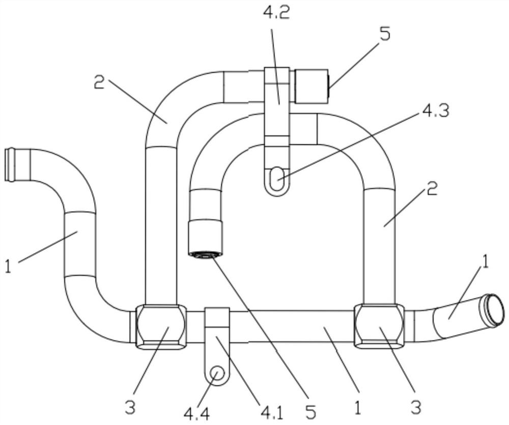
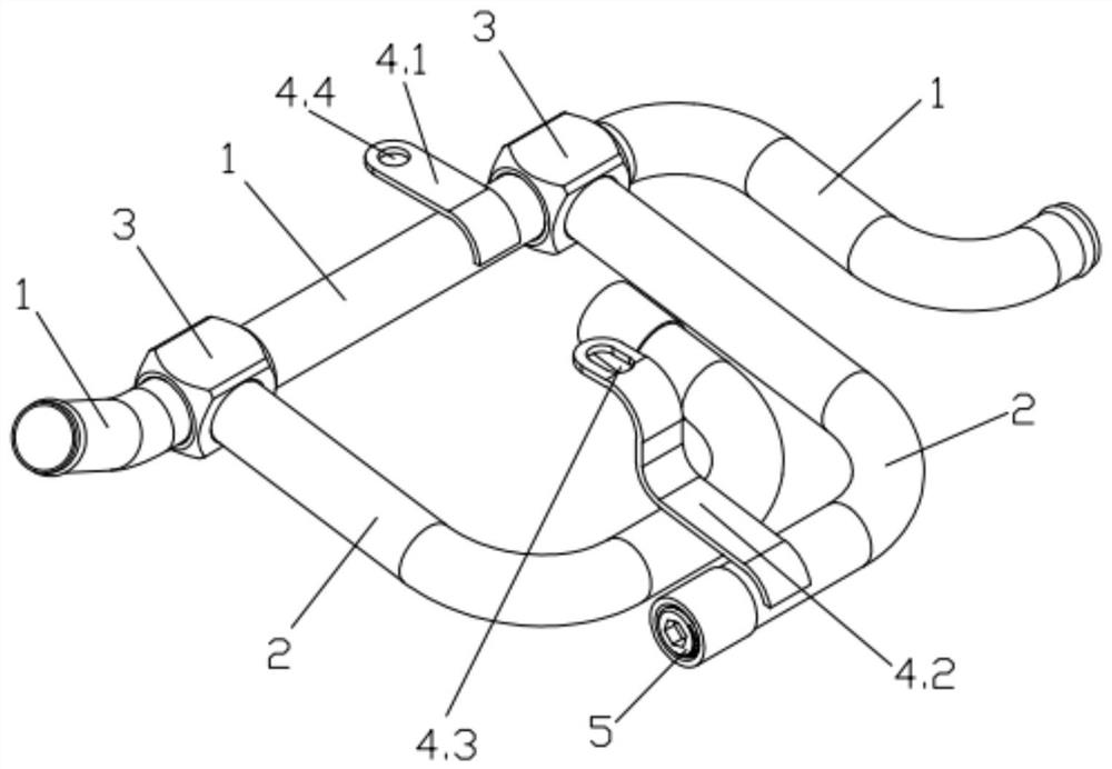
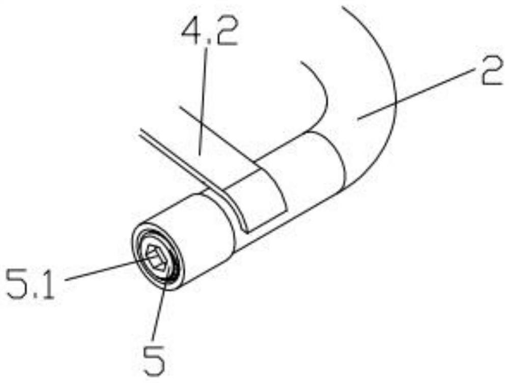
[0017] Such as figure 1 and figure 2 As shown, a tubular muffler for automobiles has two tee joints 3 welded on the vent pipe 1, two muffler pipes 2 are respectively welded on the two tee joints 3, and the ends of the muffler pipes 2 are installed There are plugs 5. Such as image 3 As shown, the middle part of the plug 5 is provided with an inner hexagonal groove 5.1, and the outer side of the plug 5 and the end of the muffler pipe 2 are provided with matching threads, and the plug 5 can be easily installed on the muffler pipe by using a hexagonal wrench ...


PUM


Abstract

The invention provides a tubular muffler for an automobile. Muffling tubes are connected with a breather pipe through a three-way connector; plugs are arranged at the tail ends of the muffling tubes; and the length of each muffling tube meets the formula: L=(2n-1)c/4lambda, wherein n is a positive integer of 1, 2, 3..., L is the length of the tube, c is the sound velocity, and lambda is the peak noise wave length. Integrated supports with kidney-shaped holes are arranged on the outer sides of the muffling tubes; the plugs are installed at the tail ends of the muffling tubes through threaded structures; and hexagon socket head grooves are formed in the middles of the plugs. The peak noise of air in the breather pipe is eliminated by using the standing wave resonance principle of sound waves in the channels of muffling tubes; and the two or more muffling tubes are welded to the breather pipe, and therefore, the noise corresponding to two or more peak frequencies can be eliminated. The tubular muffler is simple in structure; the operation of integrating and assembling the tubular muffler with other parts is simple; maintenance is facilitated; the reliability is high; and the noise eliminating effect is remarkable.

Description

technical field [0001] The invention belongs to the technical field of noise control, in particular to the field of noise control of an air intake pipeline system of a light commercial vehicle. Background technique [0002] With the rapid development of the automobile industry in recent years, the state enforces noise and third-stage fuel consumption standard control on light commercial vehicles. [0003] At present, there will be intake noise in the intake pipeline of light commercial vehicles, and the velocity pulsation or pressure pulsation excitation of the gas in the pipeline will cause gas sound radiation at the intake port of the reciprocating compressor, that is, intake noise; the intake noise of the air compressor The rear end of the air pipe is connected with an air induction pipe, and the grille of the air induction pipe is connected to the atmospheric end, so the intake noise generated by the air intake pipe will be amplified after passing through the air inducti...

Claims


Application Information

Patent Timeline
Patent Type & Authority Applications(China)
IPC IPC(8): F01N1/02F01N13/18
CPCF01N1/02F01N13/1805
Inventor 张宇翔刘虎程伟纪辉姚佳佳陈纪陈清华陈期高沈震宇王元欣夏晨晏红张倩茹陈乐乐裴帆陈鹏
Owner DONGFENG AUTOMOBILE COMPANY
Why Eureka
Try Eureka