Screen cleaning equipment
A technology for cleaning equipment and screens, which is applied to the cleaning method using liquid, the cleaning method using tools, and the removal of smoke and dust, etc., which can solve the problem of single cleaning function, achieve comprehensive cleaning, enrich the use function, and improve the practicality Effect
- Summary
- Abstract
- Description
- Claims
- Application Information
AI Technical Summary
Problems solved by technology
Method used
Image

Examples
Embodiment 1
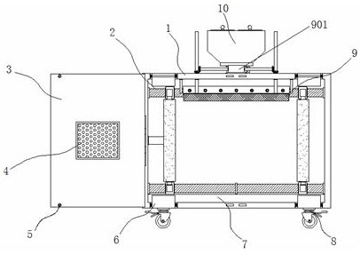
[0035]Example 1: SeeFigure 1-6The cleaning apparatus of a screen includes a housing 1, the door panel 3, and the universal wheel 8, and one end inside the housing 1 is provided with a cleaning mechanism 2. The four corners of the other end of the housing 1 are provided with a clamping. Structure 6, the bottom end of the housing 1 is fixed to the waste liquid tank 7, and the four corners of the outer bottom end of the housing 1 are fixed, and the universal wheel 8 is fixed, respectively, and one end of the top of the housing 1 is provided with a scraper mechanism 9. The inside of the top end of the housing 1 is provided with a spraying mechanism 10, and a dust collector is provided on both sides of the other end of the casing 1;
[0036]SeeFigure 1-6One screen cleaning device also includes a dust collecting mechanism, a dust collecting mechanism including a door panel 3, and the door panel 3 is movable on both sides of the other end of the housing 1, and the interior of the door panel 3...
Embodiment 2
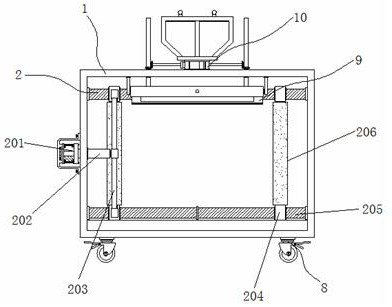
[0038]Example 2: The cleaning mechanism 2 consists of a hydraulic cylinder 201, a telescoping rod 202, a fixing rod 203, a slider 204, a first screw 205, and a brush cartridge 206, and the first screw 205 is actively attached to the top of one end of the inside of the housing 1. The first screw 205 is attached to the bottom, and both sides outside the first screw 205 are differentially coupled to the slider 204, and one end between the slider 204 is fixedly connected to the fixed bar 203, and the fixed bar 203 and the housing 1 are fixedly connected. The active connection between the sides of the telescopic rod 202, and the side of the telescopic rod 202 is fixed to the inner wall of the housing 1, and the hydraulic cylinder 201 can be used, the model number of the hydraulic cylinder 201 can be BMA-3-75-5, the slider 204 The other end of the block is attached to the brush cartridge 206;
[0039]The first screw 205 is embedded inside the slider 204, and the slider 204 is in the same hor...
Embodiment 3
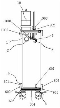
[0042]Example 3: The clamping structure 6 is composed of a slide groove 601, a pullers 602, a guide wheel 603, a connecting rope 604, a spring shaft 605, a block 606, and a limiting block 607, and the chute 601 is disposed inside the housing 1, respectively. At the four corners between the terminals, the internal activity of one end of the chute 601 is connected to the pullers 602, and the movable wheel 603 is attached between the two sides of the inner portion of the chute 601, and there is between the other ends of the other end inside the slide 601. The activity is connected to the spring shaft 605, and the spring shaft 605 is fixed between the guiding wheel 603 and the end connection between the guide wheel 603 and the connecting rope 604 is fixed, and one end of the spring shaft 605 is fixedly coupled with the block 606, and the limit block 607 is fixed, respectively. At both sides of the bottom end and the top end in the housing 1;
[0043]Specifically, such asfigure 1 withfigure...
PUM
 Abstract
Description
Claims
Application Information
 - R&D
- Intellectual Property
- Life Sciences
- Materials
- Tech Scout
- Unparalleled Data Quality
- Higher Quality Content
- 60% Fewer Hallucinations
Browse by: Latest US Patents, China's latest patents, Technical Efficacy Thesaurus, Application Domain, Technology Topic, Popular Technical Reports.
© 2025 PatSnap. All rights reserved.Legal|Privacy policy|Modern Slavery Act Transparency Statement|Sitemap|About US| Contact US: help@patsnap.com